Comprehensive Guide to Case 1835C Parts Diagram
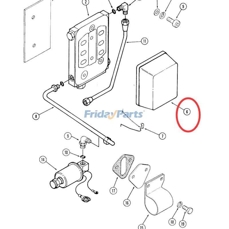
The world of heavy machinery encompasses a vast array of intricate elements that work in harmony to ensure optimal performance. For operators and technicians, grasping the layout and functionality of these essential components is crucial for effective maintenance and troubleshooting. A clear visual representation of these mechanisms can greatly enhance one’s understanding of how they interact within the overall system.
In this section, we will delve into the specific assemblies that comprise a particular model, highlighting the significance of each unit and its contribution to the machinery’s efficiency. By examining the relationships between various elements, readers will gain insights into the operational dynamics and potential areas for improvement.
Whether you are a seasoned professional or an enthusiastic learner, familiarity with these configurations will empower you to tackle challenges more effectively. A comprehensive overview not only aids in the identification of components but also enhances your ability to execute repairs and upgrades confidently.
Understanding Case 1835c Components
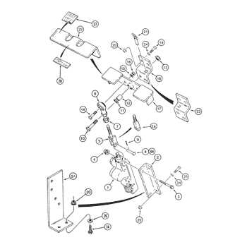
Comprehending the individual elements of heavy machinery is crucial for effective maintenance and operation. Each component plays a vital role in ensuring optimal performance and longevity of the equipment. This section delves into the essential elements that constitute the machinery, highlighting their functions and interrelations.
Key Components Overview
- Engine: The powerhouse of the machine, responsible for converting fuel into mechanical energy.
- Transmission: This system facilitates the transfer of power from the engine to the wheels, enabling movement.
- Hydraulic System: A critical mechanism that utilizes fluid pressure to perform tasks such as lifting and moving heavy loads.
- Frame: The structural backbone providing stability and support for all other components.
- Controls: The interface through which operators manage the machine’s functions, ensuring efficient operation.
Functions of Major Elements
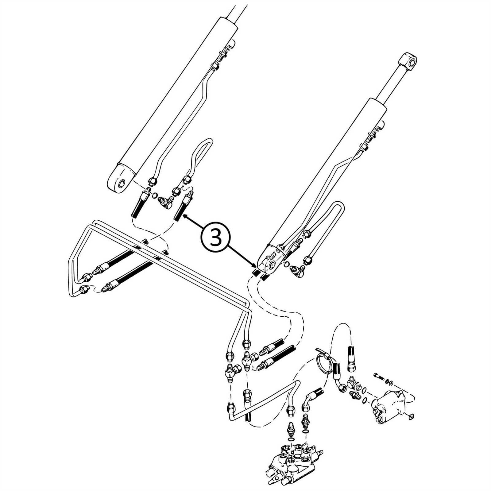
- Engine: Converts fuel into kinetic energy, influencing the machine’s speed and efficiency.
- Transmission: Aids in gear shifting and regulates the speed of the machinery.
- Hydraulic System: Powers attachments and implements, enhancing versatility.
- Frame: Supports weight and absorbs stress during operation, contributing to safety.
- Controls: Provides real-time feedback to the operator, crucial for decision-making.
Understanding these components and their interactions is fundamental for anyone looking to maintain or operate the machinery effectively. Proper knowledge can lead to better decision-making and improved operational efficiency.
Importance of Parts Diagrams
Understanding the components and their relationships within a mechanical system is crucial for effective maintenance and repair. Visual representations that illustrate each element provide clarity and assist in identifying issues more swiftly. These resources serve not only as guides but also as educational tools for both novice and experienced technicians.
Facilitating Maintenance
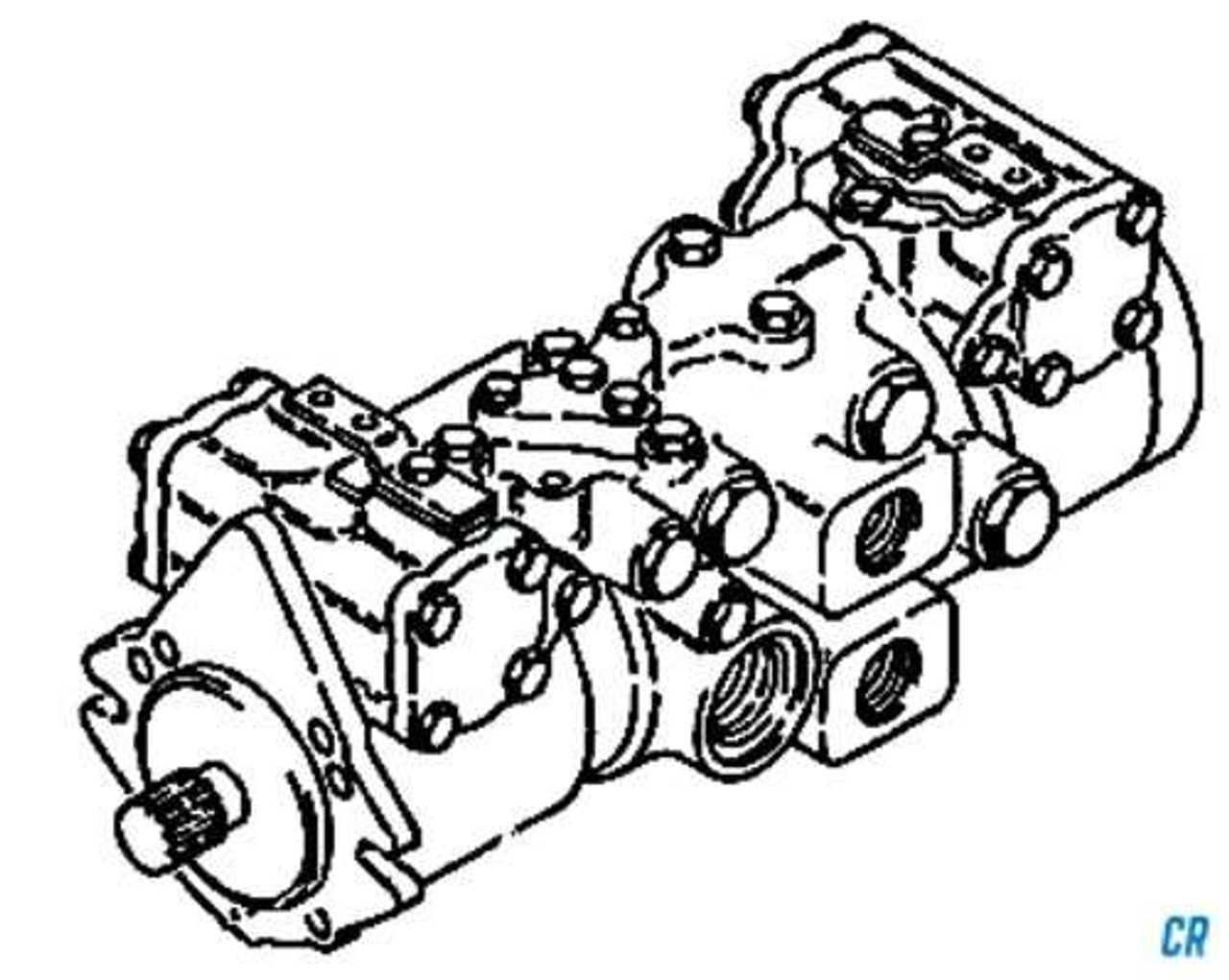
Having a visual reference allows for easier identification of components during inspections and repairs. Technicians can quickly locate specific items, reducing the time spent troubleshooting. This efficiency ultimately leads to decreased downtime and enhanced productivity, essential in any operational setting.
Enhancing Understanding
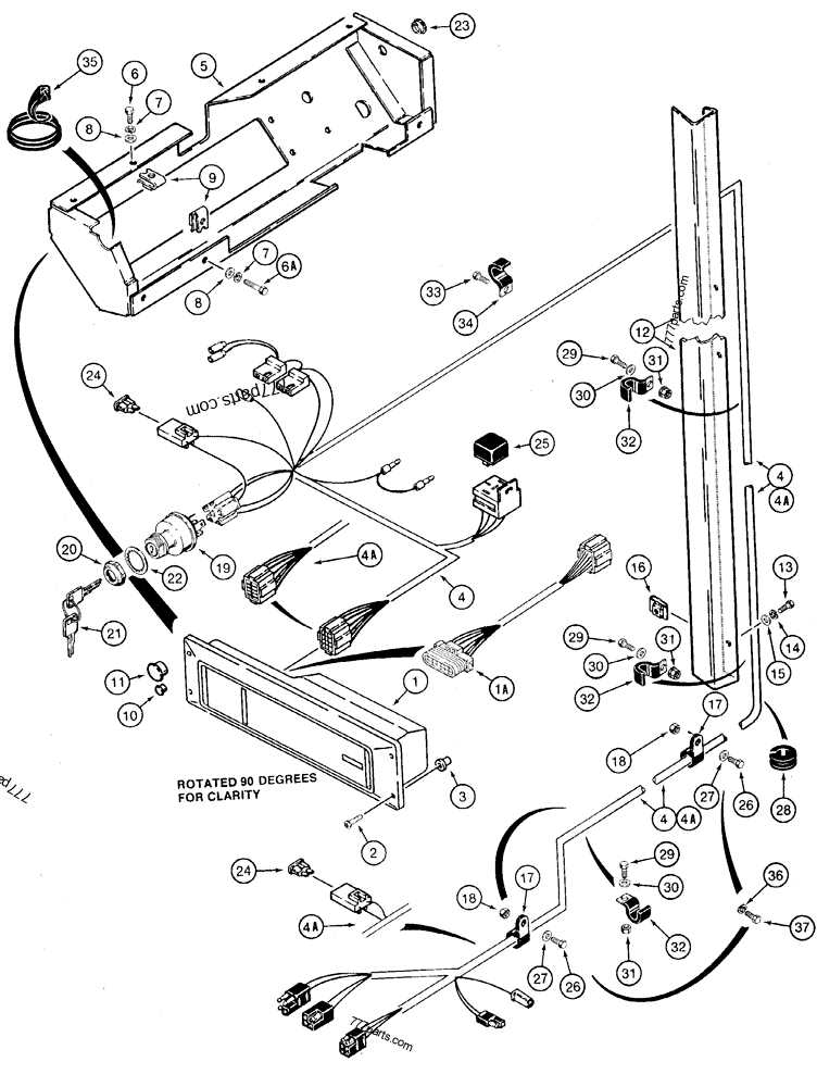
Visual aids contribute significantly to a deeper comprehension of how various elements interact within a system. By breaking down complex machinery into understandable parts, these illustrations help in training new personnel and improving overall knowledge within a team. This understanding fosters better decision-making when addressing repairs or upgrades.
How to Read Diagrams Effectively
Understanding visual representations is crucial for anyone working with complex machinery or systems. These illustrations serve as a guide, providing a clear overview of components and their relationships. Mastering the ability to interpret these visuals can significantly enhance your efficiency and accuracy in troubleshooting and assembly tasks.
Key Elements to Focus On
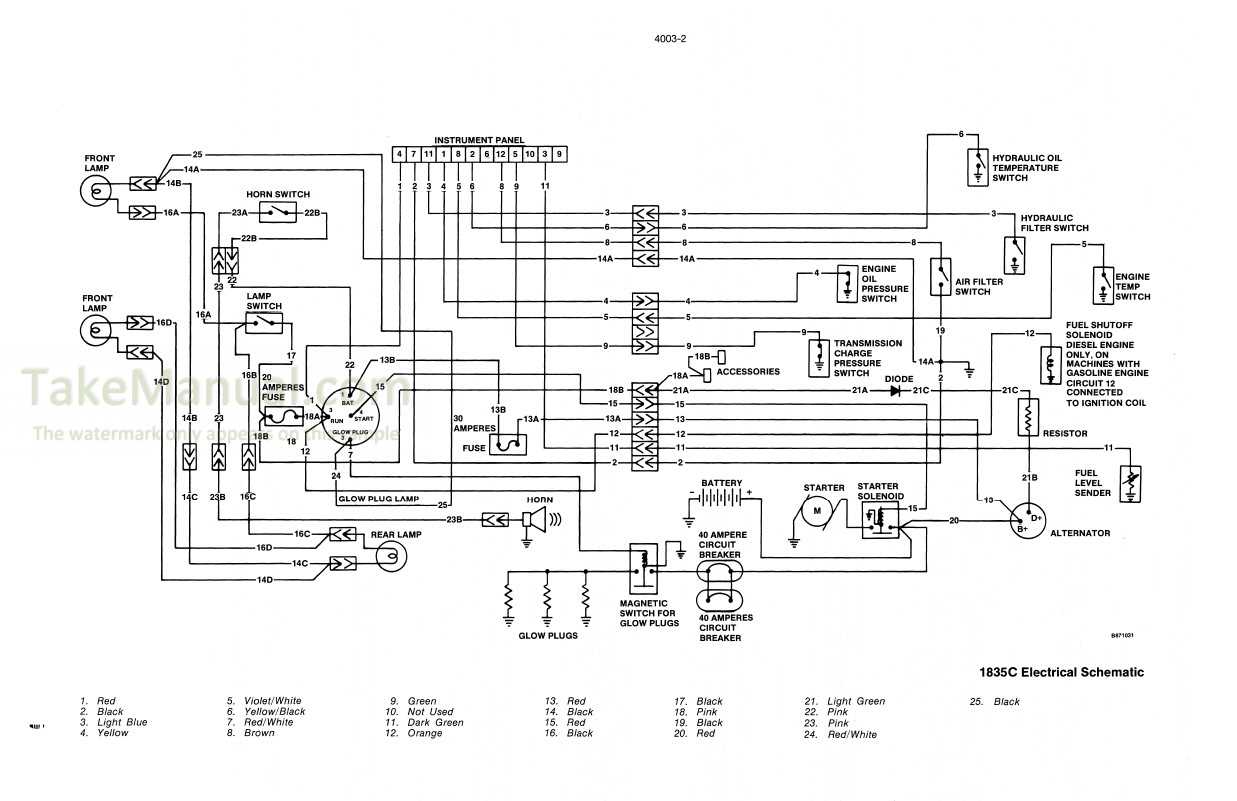
Begin by identifying the main features of the illustration. Look for legends or keys that explain symbols and colors used throughout the image. Recognizing these elements allows you to quickly understand what each part represents. Additionally, pay attention to the layout; often, it reflects the logical sequence of assembly or operation, guiding you through the process step-by-step.
Practice and Familiarity
Frequent exposure to different types of visual guides will improve your interpretation skills over time. Try to practice by working on various examples. As you become more familiar with common symbols and layouts, your ability to decode these representations will grow. Consider using additional resources, such as tutorials or instructional videos, to further enhance your understanding and build confidence.
Common Issues with Case 1835c Parts
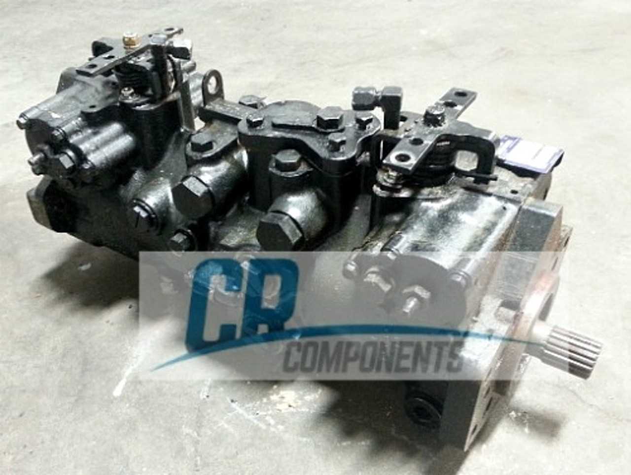
When operating heavy machinery, it’s not uncommon to encounter various complications related to components. These challenges can stem from wear and tear, improper installation, or even design flaws. Addressing these issues promptly is essential for maintaining efficiency and ensuring safety in operations.
Wear and Tear: Over time, certain elements can deteriorate due to constant use. For instance, hydraulic seals and hoses may develop leaks, leading to reduced performance and potential damage to other systems. Regular inspection and timely replacement can mitigate these risks.
Improper Installation: Components that are not installed correctly can cause operational failures. Misalignment or incorrect torque specifications can lead to premature failure. It is crucial to follow manufacturer guidelines and seek professional assistance if needed.
Design Flaws: Occasionally, specific designs may not hold up under strenuous conditions, leading to repeated issues. Identifying these weaknesses and seeking aftermarket solutions or upgrades can enhance reliability and performance.
Regular maintenance and attention to these common concerns can greatly extend the lifespan of the equipment and improve overall operational efficiency.
Where to Find Replacement Parts

Finding suitable components for your machinery can often be a challenging task. However, with the right resources and strategies, you can easily locate high-quality replacements to keep your equipment running smoothly. This section provides valuable insights into the best avenues for sourcing these essential items.
Online Retailers
The internet is an excellent resource for obtaining various items. Numerous websites specialize in machinery supplies, offering a vast selection of components at competitive prices. When shopping online, ensure to verify the credibility of the seller and check for customer reviews to guarantee quality and reliability.
Local Dealers and Distributors
Another effective approach is to visit local dealers or distributors. These businesses often carry a range of products suited for your machinery needs and can provide personalized assistance. Engaging with local experts can also help you identify specific components that may not be readily available online.
Maintenance Tips for Longevity
Regular upkeep is essential for ensuring the durability and performance of your machinery. By following a few straightforward practices, you can extend its lifespan and maintain optimal functionality. Here are some effective strategies to consider:
- Regular Inspections: Conduct routine checks to identify any signs of wear or damage. Addressing issues early can prevent more significant problems down the line.
- Proper Lubrication: Ensure all moving components are adequately lubricated. This reduces friction and minimizes wear, enhancing efficiency.
- Cleanliness: Keep the equipment clean from dirt, debris, and contaminants. Regular cleaning helps maintain performance and prevents corrosion.
- Follow Manufacturer Guidelines: Adhere to recommended maintenance schedules and procedures outlined by the manufacturer for optimal care.
- Use Quality Parts: When replacements are necessary, opt for high-quality components that meet or exceed the original specifications.
- Monitor Fluid Levels: Regularly check and maintain appropriate levels of hydraulic fluids, oil, and coolant to ensure efficient operation.
- Training and Operation: Ensure that all operators are well-trained and follow proper operating procedures to prevent misuse and reduce the risk of damage.
Implementing these practices will not only enhance the performance of your equipment but also ensure its longevity, saving you time and resources in the long run.
Comparing Case 1835c with Similar Models
This section delves into a comparative analysis of a particular machine and its counterparts within the same category. Understanding the distinctions and similarities among these models provides valuable insights for potential buyers and users, allowing for informed decisions based on performance, specifications, and design features.
| Feature | Model A | Model B | Model C |
|---|---|---|---|
| Engine Power | 50 HP | 48 HP | 52 HP |
| Operating Weight | 5,500 lbs | 5,300 lbs | 5,600 lbs |
| Loader Capacity | 1,500 lbs | 1,400 lbs | 1,600 lbs |
| Hydraulic Flow | 15 GPM | 14 GPM | 16 GPM |
When examining specifications such as engine power and operating weight, noticeable differences arise, impacting overall functionality and suitability for various tasks. Evaluating these factors alongside hydraulic performance can assist users in determining which model aligns best with their requirements.
Assembly Instructions for Components
This section provides a comprehensive guide for piecing together various elements of the equipment. Proper assembly ensures optimal performance and longevity of the unit. Follow the instructions carefully to achieve a seamless integration of each component.
Before starting the assembly process, ensure you have all necessary tools and components at hand. The following steps outline the procedure:
- Begin by organizing all parts according to their respective categories.
- Refer to the provided list to confirm that you have everything required.
- Identify the main base unit, which will serve as the foundation for assembly.
As you proceed, adhere to these specific instructions for each group of components:
Connecting Components
- Align the connectors precisely to ensure a secure fit.
- Use the recommended screws to attach each piece firmly.
- Double-check connections for stability before moving on.
Installing Additional Features
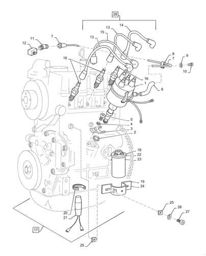
- Follow the sequence indicated in the guideline for optimal arrangement.
- Ensure that all wires are correctly routed to avoid damage.
- Test each feature individually after installation to confirm functionality.
Once all components are assembled, perform a final inspection. Make sure all parts are securely in place and that there are no loose elements. This careful approach will enhance the efficiency and durability of your assembled unit.
Aftermarket vs. OEM Parts
The choice between original and alternative components is a critical consideration for many consumers and professionals. Each option presents distinct advantages and drawbacks that can significantly impact performance, cost, and longevity.
When evaluating these options, several factors come into play:
- Quality: Original components are often manufactured to strict specifications, ensuring high quality and compatibility.
- Cost: Alternative components typically offer a lower price point, making them an attractive option for budget-conscious buyers.
- Availability: Aftermarket options can be more readily available, especially for older models, whereas original components may have limited stock.
- Warranty: Original items usually come with a manufacturer’s warranty, providing peace of mind regarding their performance.
- Performance: Some alternative components may not match the performance levels of their original counterparts, affecting overall efficiency.
In conclusion, the decision hinges on individual needs and circumstances. Weighing these factors will help determine the best choice for maintenance or replacement. Careful consideration of both options is essential for achieving optimal results.
Cost Considerations for Repairs
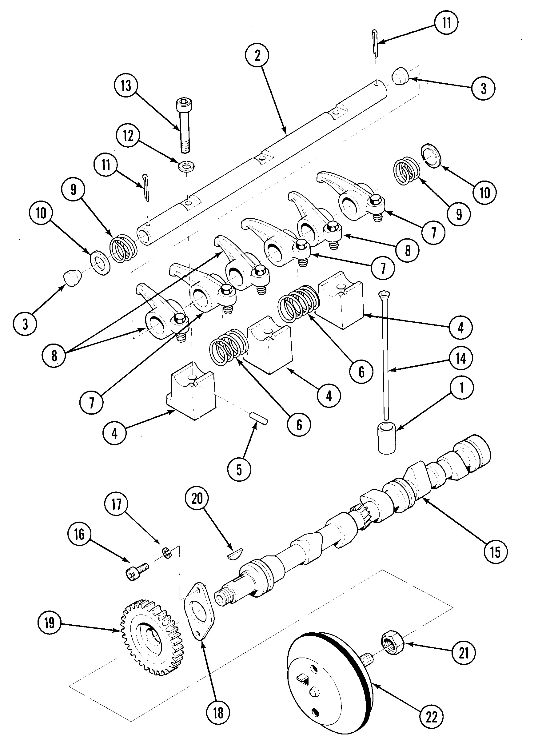
When it comes to maintenance and restoration of machinery, financial implications play a crucial role in decision-making. Understanding the various elements that contribute to overall expenses can help in budgeting effectively and ensuring that repairs are both cost-efficient and timely.
Factors Influencing Repair Costs
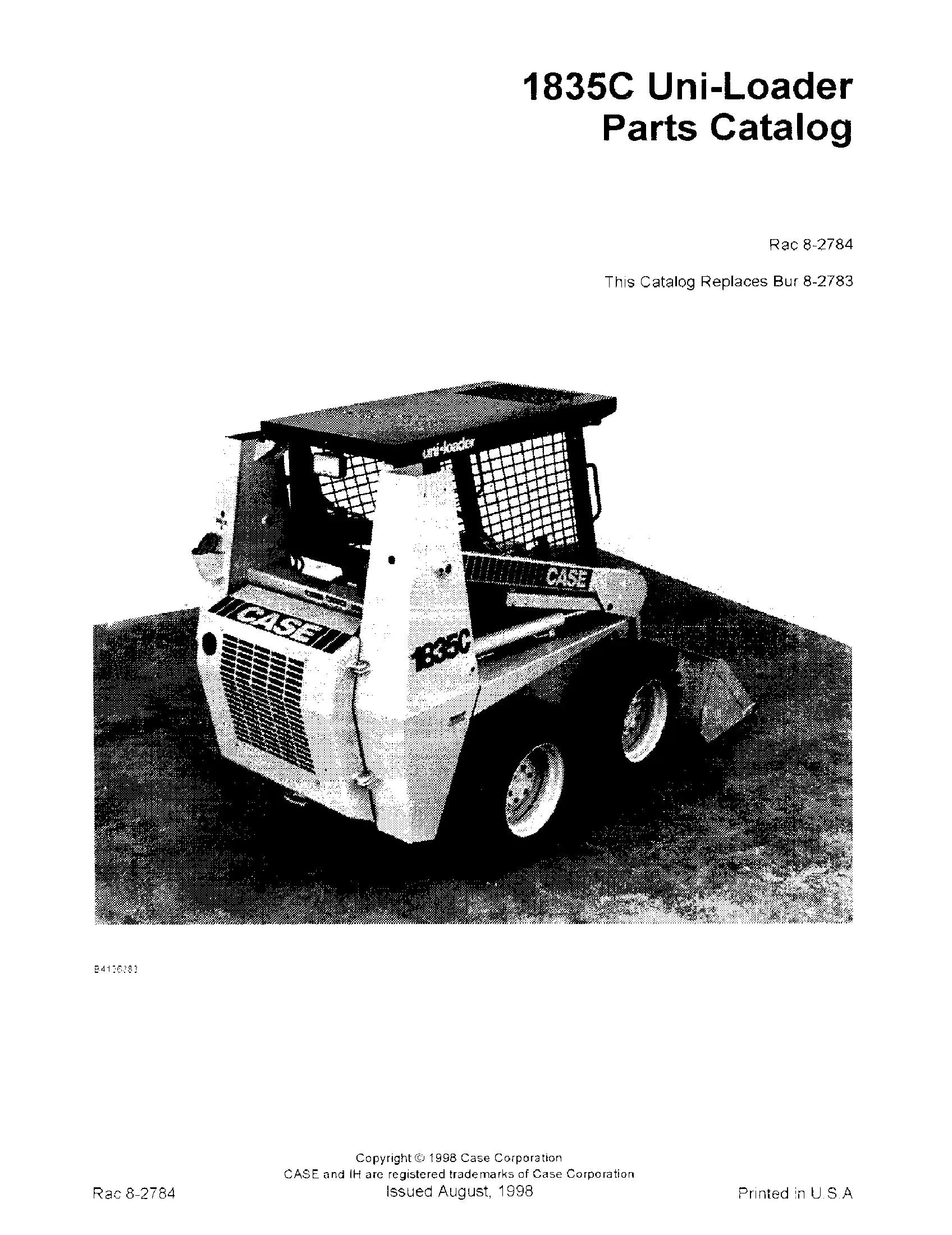
Several factors can affect the total price of repairing equipment. These include the complexity of the issue, the availability of necessary components, and labor charges. Additionally, choosing between original equipment manufacturer (OEM) parts and aftermarket alternatives can significantly impact costs.
| Factor | Impact on Cost |
|---|---|
| Complexity of Repair | Higher complexity may lead to increased labor time and expertise required. |
| Parts Availability | Rare components may incur additional shipping and handling fees. |
| Labor Rates | Varies by location and technician experience, affecting overall expenses. |
| OEM vs Aftermarket | OEM parts are often more expensive but can offer better reliability. |
Budgeting for Unexpected Expenses
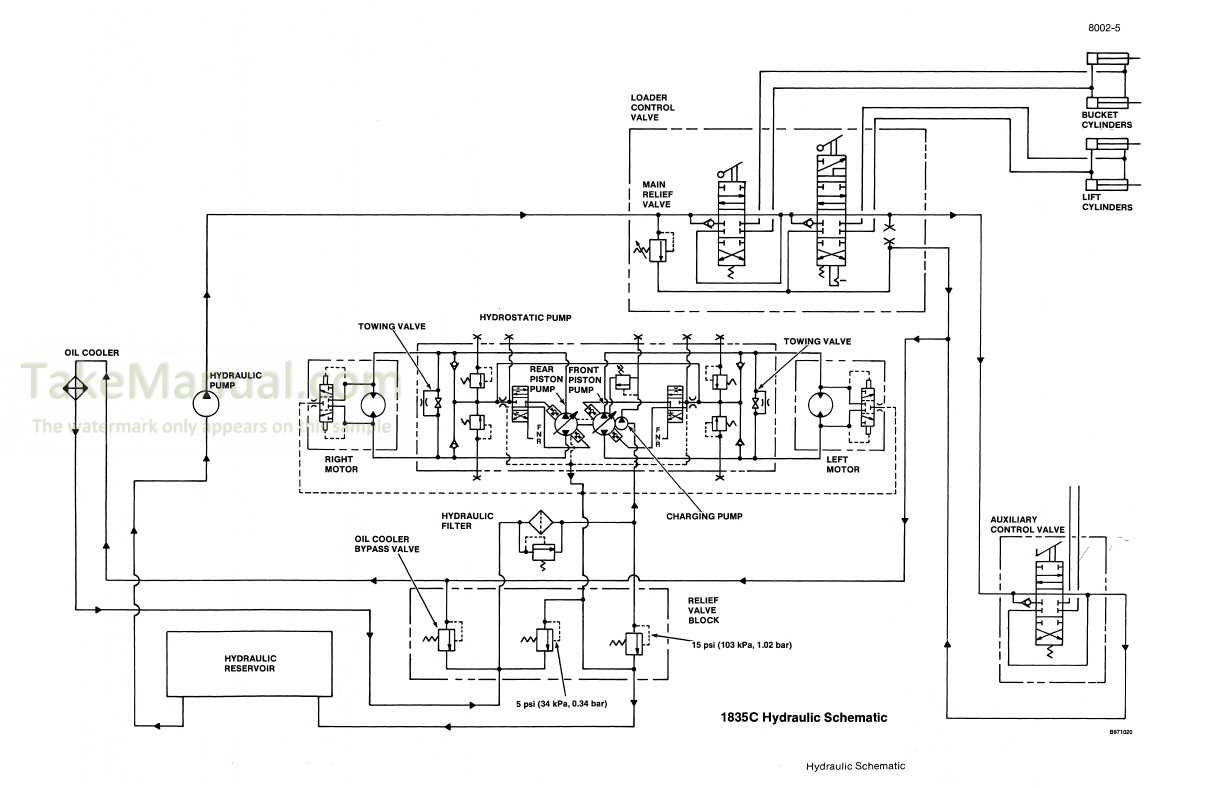
It is essential to account for potential unforeseen costs that may arise during the repair process. Unexpected complications can lead to additional parts or labor, necessitating a buffer in the budget. Establishing a contingency fund can provide peace of mind and financial flexibility during repairs.