Comprehensive Guide to John Deere 1050 Parts Diagram
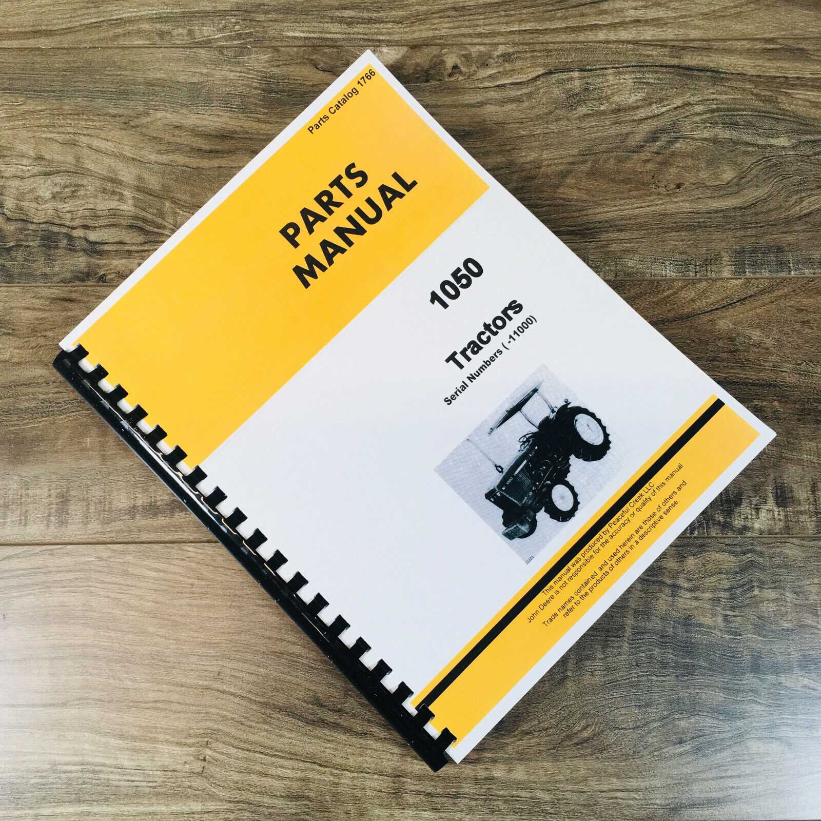
In complex mechanical systems, it is crucial to understand how individual elements fit together to ensure optimal performance. Identifying and interpreting the layout of various mechanisms can greatly simplify maintenance and repairs, allowing for a more efficient workflow.
When navigating through a machine’s structure, it’s important to familiarize yourself with the placement and interaction of its key components. Recognizing these connections enables a better understanding of how the system functions as a whole, helping to streamline troubleshooting and improve overall efficiency.
By exploring the arrangement of essential elements, operators and technicians can ensure that all sections are working in harmony. This not only aids in maintaining peak performance but also enhances the longevity of the equipment through more informed and precise interventions.
John Deere 1050 Parts Diagram Overview
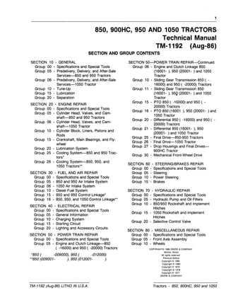
Understanding the intricate layout of various components within a mechanical system is crucial for effective maintenance and repair. A visual guide provides a structured way to identify and analyze each element’s position and function within the larger assembly. By utilizing this approach, users can efficiently locate specific items and understand their relationships within the system, aiding in troubleshooting and replacements.
Key Components Layout
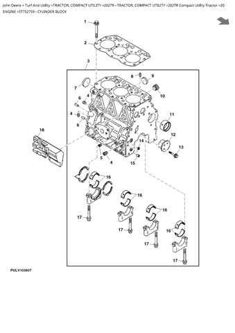
The detailed arrangement showcases essential elements, each playing a vital role in the overall functionality. The structured guide allows for easy identification of these elements, streamlining both repair and routine upkeep. Every section is clearly marked, ensuring that even complex assemblies can be navigated with ease.
Ensuring Proper Maintenance
Having a clear understanding of the assembly’s structure not only simplifies repair tasks but also ensures long-term operational reliability. By referencing a clear visual guide, users can maintain optimal performance and address potential issues before they escalate.
Identifying Key Components in the Diagram
Understanding the layout of machinery requires a clear overview of its essential elements. By examining the visual representation, it becomes easier to pinpoint crucial sections that contribute to the overall functionality of the equipment. Each component plays a specific role in maintaining smooth operation, and recognizing these elements can aid in repairs, replacements, and general maintenance.
| Component | Function |
|---|---|
| Engine Block | Provides the core power for machinery operation |
| Hydraulic Pump | Controls fluid flow to various mechanical systems |
| Drive Shaft | Transfers rotational force from the motor to other parts |
| Cooling System | Regulates engine temperature to prevent overheating |
| Transmission | Ensures appropriate power distribution for movement |
Understanding the Hydraulic System Layout
The hydraulic configuration of any machinery plays a crucial role in its functionality, ensuring smooth power transmission through fluid mechanics. By understanding the arrangement of key elements within this system, one can gain insights into how pressure is controlled, distributed, and utilized to drive various operations. A clear grasp of this setup enables effective maintenance and troubleshooting.
Main Components of the Hydraulic System
- Pumps – Responsible for converting mechanical energy into hydraulic energy by pressurizing the fluid.
- Valves – These regulate the flow and pressure, allowing the system to operate efficiently and safely.
- Cylinders – Convert hydraulic energy back into mechanical movement, typically in the form of linear motion.
Flow and Pressure Control
- Fluid is drawn into the pump from a reservoir.
- The pump pressurizes the fluid and sends it through a network of hoses and pipes.
- Valves adjust flow rates and pressure levels, ensuring precise control of the system’s output.
- Cylinders and motors act upon the pressurized fluid to perform mechanical tasks, such as lifting or pushing.
Breakdown of the Engine Assembly
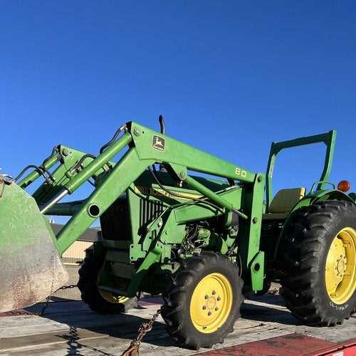
The complex structure of the power unit consists of several key elements that work together to ensure optimal functionality. Each component plays a specific role, contributing to the overall efficiency and reliability of the machine.
At the core of this setup are mechanisms responsible for converting fuel into energy, while surrounding systems handle the regulation of temperature and the proper flow of fluids. Ensuring each element is in proper working condition is critical for maintaining the smooth operation of the entire assembly.
Further exploration of individual parts reveals how different systems, such as ignition and cooling, are intricately connected, creating a seamless workflow that powers the entire machinery.
Exploring the Electrical System Connections
The arrangement of the electrical components in a machine plays a crucial role in its functionality. By understanding how different elements are interconnected, you can gain insights into how power flows and how various systems communicate within the structure.
Key connections within the electrical setup often include critical paths for energy distribution, as well as control mechanisms. Below is an overview of some typical components and their roles in ensuring smooth operation:
- Power Source: This element supplies energy to the entire system, ensuring that all components receive the necessary voltage to function.
- Wiring Harness: A structured set of cables that transmits electrical signals between different parts, enabling communication and control.
- Fuses and Relays: These protective components help prevent overloads and ensure that electrical currents are directed safely and efficiently.
- Switches: These are used to control the flow of electricity, allowing the operator to manage different functions.
- Connectors: Secure joints that link wires and components together, ensuring stable electrical paths.
- Steering Wheel: The primary interface for the operator, allowing for direction changes.
- Steering Column: Connects the wheel to the gearbox, transmitting the operator’s input.
- Gearbox: Converts the rotational motion from the steering wheel into lateral movement.
- Linkage System: Connects the gearbox to the front wheels, facilitating their movement.
- Wheel Assembly: The final point of contact with the ground, responsible for executing turns.
- Brake Pedal: The interface for the operator, which initiates the braking process.
- Brake Cylinder: A hydraulic unit that amplifies the force applied to the pedal.
- Brake Shoes: Friction materials that press against the drum or disc to create stopping power.
- Brake Lines: Tubing that carries hydraulic fluid to the cylinders, facilitating the operation of the brakes.
- Check fluid levels, including oil, coolant, and fuel.
- Inspect belts and hoses for signs of wear or damage.
- Look for any leaks around the engine or hydraulic components.
Fuel System Components and Placement
The efficient functioning of any machinery relies heavily on the correct arrangement and integration of its fuel system elements. Understanding how these components interact and where they are situated within the overall structure is crucial for optimal performance and maintenance. Each element plays a vital role in ensuring that fuel is properly delivered and utilized within the engine, contributing to its effectiveness and longevity.
Among the key components of this system are the fuel tank, pump, filters, and injectors. The fuel tank serves as the reservoir for the energy source, while the pump is responsible for transporting the fuel to the engine. Filters play an essential role in removing impurities from the fuel, safeguarding the engine from potential damage. Finally, the injectors ensure precise delivery of the fuel into the combustion chamber, allowing for efficient ignition and operation.
Placement of these components is equally important. The fuel tank is typically positioned in a location that maximizes gravity feed, while the pump is strategically placed to minimize the distance the fuel must travel. Filters are often located close to the tank to catch contaminants early, and injectors are situated directly at the entry points of the engine for immediate and efficient fuel delivery.
Transmission and Gearbox Arrangement
The arrangement of the transmission and gearbox is crucial for ensuring smooth operation and optimal performance in machinery. This system is responsible for transferring power from the engine to the wheels, facilitating the desired speed and torque. A well-designed configuration not only enhances efficiency but also contributes to the longevity of the equipment.
Understanding the components involved in this assembly is essential for maintenance and troubleshooting. Gear ratios, for instance, play a significant role in determining how effectively power is delivered. The interplay between different gears allows for adjustments in speed and torque, catering to various operational requirements.
Moreover, the alignment and condition of the gearbox can significantly impact overall performance. Regular inspections and timely replacements of worn-out components are vital practices to ensure that the transmission system functions optimally. Knowledge of the layout and functioning of this arrangement can aid operators in making informed decisions regarding maintenance and repairs.
Cooling System Parts and Functions
The effective operation of any machinery heavily relies on its thermal management mechanism. A well-designed cooling setup ensures that the engine and related components operate within optimal temperature ranges, preventing overheating and promoting longevity. Understanding the key components of this system is essential for maintaining functionality and efficiency.
Radiator plays a crucial role by dissipating heat from the coolant fluid as it circulates through the system. It allows the heat to escape into the atmosphere, ensuring the engine remains at a stable temperature. Additionally, the water pump facilitates the movement of coolant throughout the engine and radiator, maintaining a consistent flow that is vital for temperature regulation.
Another important element is the thermostat, which regulates the flow of coolant based on the engine’s temperature. When the engine reaches a predetermined temperature, the thermostat opens, allowing coolant to flow into the radiator for cooling. Furthermore, coolant hoses connect various components, ensuring the smooth transfer of the cooling fluid while withstanding high pressures and temperatures.
In summary, the cooling assembly comprises several interconnected elements, each serving a specific purpose in maintaining the engine’s thermal equilibrium. Proper functioning of these components is essential for the overall performance and reliability of the machine.
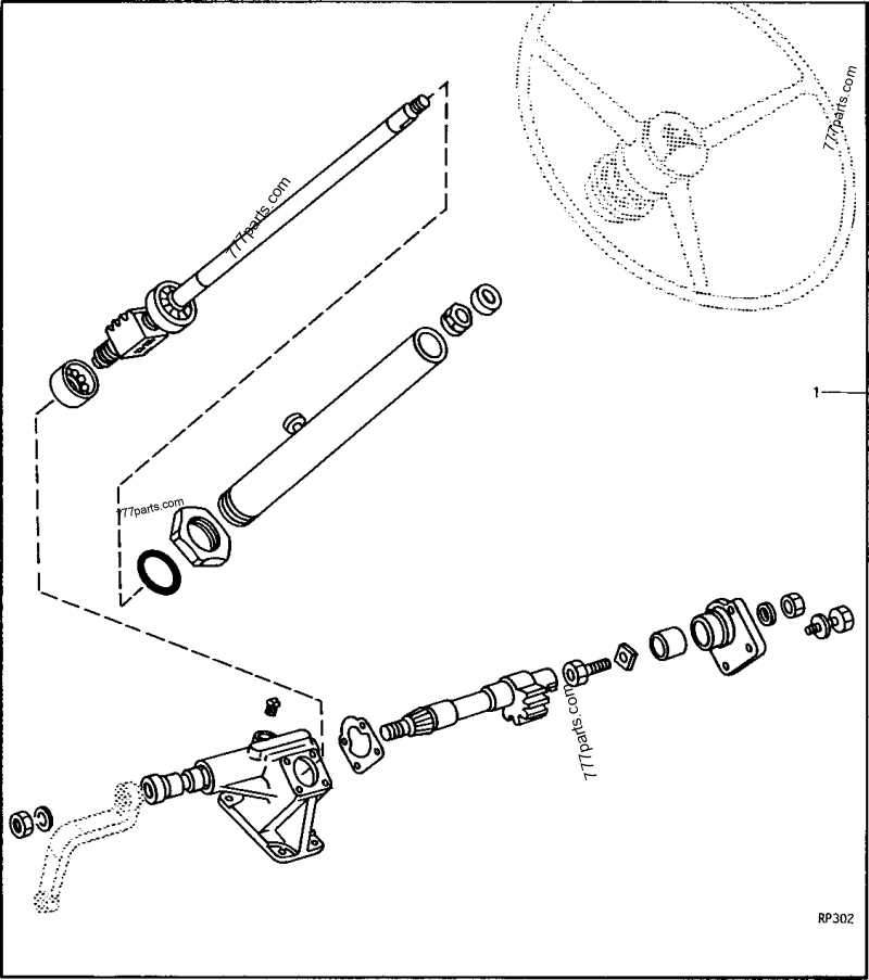
Detailed View of Steering Mechanism
The steering system of a vehicle is a crucial component that facilitates maneuverability and control. It consists of various elements that work together to enable precise navigation, ensuring that the machine can respond effectively to the operator’s commands. Understanding the intricacies of this mechanism is essential for proper maintenance and repair.
Key Components of the Steering System
Functionality of the Steering Assembly
The steering assembly operates on the principle of leverage, enabling efficient control with minimal effort. As the operator turns the steering wheel, the gearbox adjusts the angle of the front wheels, allowing the vehicle to navigate curves and corners smoothly. Regular inspections and maintenance of this assembly are vital to ensure optimal performance and safety.
Brake System Structure and Operation
The brake mechanism is a crucial component of any vehicle, ensuring safety and control during operation. It is designed to effectively slow down or stop the machine by converting kinetic energy into heat. Understanding the layout and functionality of this system is essential for maintenance and troubleshooting.
Components of the Brake Mechanism
The braking system consists of several key elements, each playing a vital role in its overall performance. Major components include:
How the System Operates
When the operator presses the pedal, hydraulic fluid is pushed through the brake lines to the brake cylinder. This action generates pressure, causing the brake shoes to expand and contact the drum or disc. The friction produced effectively slows down the wheels, enabling the vehicle to come to a stop. Regular inspection and maintenance of these components are essential to ensure optimal performance and safety.
Maintenance Tips for John Deere 1050
Proper upkeep is essential for ensuring the longevity and efficiency of agricultural machinery. Regular attention not only enhances performance but also minimizes the risk of unexpected breakdowns. By adhering to systematic maintenance protocols, operators can preserve the functionality and reliability of their equipment.
Regular Inspection
Frequent examinations of your machinery can help identify potential issues before they escalate. Consider the following steps:
Scheduled Servicing
Establishing a routine service schedule is vital for optimal performance. Make sure to:
- Change oil and filters as recommended in the owner’s manual.
- Replace air filters to ensure proper airflow.
- Lubricate all moving parts to prevent friction and wear.
By following these maintenance tips, operators can significantly extend the lifespan of their agricultural equipment and enhance overall productivity.