6.7 Powerstroke Engine Parts Diagram Explained

The inner workings of modern diesel technology have evolved significantly over the years. These advancements have allowed for better efficiency, improved power delivery, and enhanced reliability. To truly grasp how these systems function, it is essential to explore the key elements that work in unison to produce optimal performance. By examining the relationships between various components, one can gain a deeper appreciation for the intricate design and engineering involved.
Each part plays a critical role in maintaining the balance and efficiency of the whole mechanism. From fuel management systems to cooling mechanisms, the integration of these elements ensures that the machine operates smoothly under different conditions. Delving into the structure of this system provides valuable insights into how
Powerstroke Engine Overview
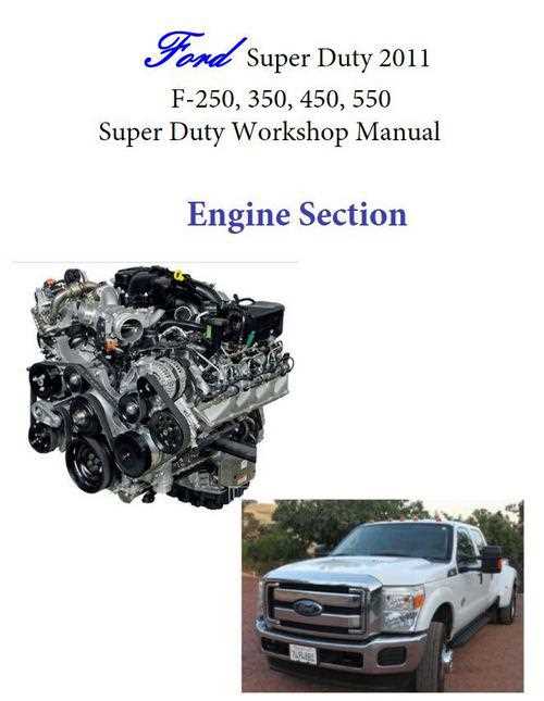
In modern diesel technology, efficiency and durability are key factors driving the evolution of power units. The advanced design focuses on delivering high torque, enhanced fuel economy, and reduced emissions, making it ideal for heavy-duty applications. These systems are engineered to withstand rigorous conditions while maintaining optimal performance, ensuring reliability in demanding environments.
| Feature | Description | |||||||||||||
|---|---|---|---|---|---|---|---|---|---|---|---|---|---|---|
| Fuel System | Optimized for precision, allowing for better fuel injection and overall combustion efficiency. | |||||||||||||
| Cooling Mechanism | Advanced thermal management ensures consistent temperature control, enhancing long-term stability. | |||||||||||||
| Turbocharger | Main Components of the 6.7 Powerstroke
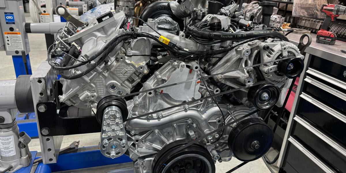
The internal structure of this diesel powerhouse consists of several key elements working together to ensure reliable performance. These components form the foundation of its functionality, optimizing both power output and fuel efficiency. Understanding these core elements is essential for maintaining peak operation and addressing potential issues. Cylinder BlockThe cylinder block is the central framework that houses critical components like pistons and crankshafts. It’s designed to withstand extreme pressures and temperatures, ensuring durability during high-stress conditions. Its robust construction provides stability and forms the backbone of the entire system. Turbocharger System
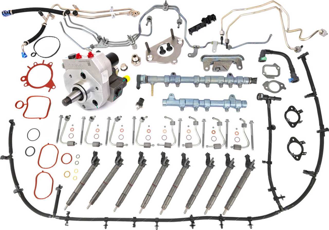
A vital component that enhances the air intake process, the turbocharger significantly boosts performance by forcing more air into the combustion chamber. This allows for greater fuel combustion efficiency, increasing overall power without compromising fuel economy. The turbo system is engineered to deliver consistent performance, especially under heavy loads. Fuel System Layout in the 6.7 PowerstrokeThe fuel system in this diesel-powered platform is designed to efficiently deliver diesel to the combustion chambers, ensuring optimal performance and fuel efficiency. By coordinating the various components involved in fuel delivery, the system provides a steady and precise flow of fuel under different driving conditions. Key components work together to pressurize and deliver diesel to the injectors, which atomize the fuel for efficient combustion. Below is a basic layout of the system, illustrating the role of each part:
Lubrication Flow Process
The lubricant flows from the sump through the oil pump, which draws in and pressurizes it. Once pressurized, the fluid is directed through the oil filter to remove impurities before entering the main lubrication channels. From there, it reaches essential parts such as bearings, pistons, and camshafts, providing necessary lubrication. After fulfilling its role, the lubricant returns to the sump, where the cycle begins anew. Air Intake System Design in the 6.7 PowerstrokeThe air intake configuration is a critical aspect of optimizing performance in modern diesel vehicles. It directly influences the efficiency and power output by ensuring that the combustion chamber receives an adequate supply of clean air. The design of this system incorporates various components working in unison to enhance airflow and filtration, ultimately contributing to the vehicle’s overall capabilities. Components and Functionality
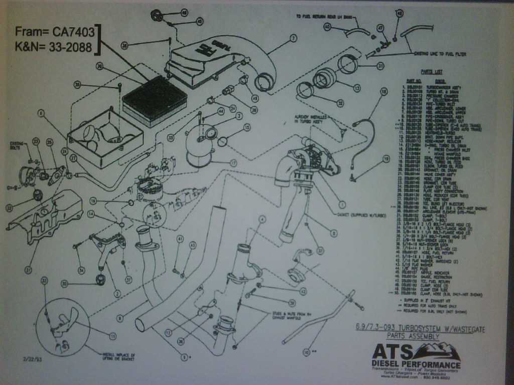
The intake system consists of several key elements, including the air filter, intake manifold, and various ducts. The air filter is designed to prevent contaminants from entering the combustion chamber, promoting longevity and efficiency. Following the filter, air travels through the intake manifold, which is engineered to distribute airflow evenly across cylinders. This design ensures optimal combustion, maximizing power and minimizing emissions. Performance Enhancements
Innovative features such as variable geometry in the intake design allow for adjustments based on engine load and speed. This adaptability enhances overall efficiency, ensuring that the system can respond dynamically to different driving conditions. Moreover, the integration of advanced materials helps reduce weight while maintaining structural integrity, further improving performance metrics. Electronic Control Modules in Powerstroke Engines
Electronic control modules play a pivotal role in modern automotive systems, serving as the brains that orchestrate various functions to optimize performance and efficiency. These sophisticated components monitor and regulate critical aspects, ensuring that vehicles operate smoothly under diverse conditions. Functions of Control Modules
The main responsibilities of electronic control modules include:
Types of Control ModulesThere are several types of control modules that work together to enhance vehicle performance:
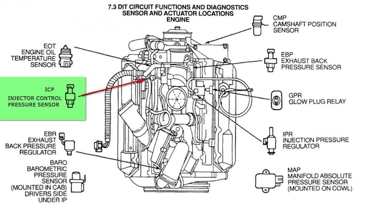
Understanding these modules is essential for diagnosing issues and performing upgrades, as they significantly influence vehicle dynamics and efficiency. Transmission Integration with the 6.7 PowerstrokeThe seamless connection between the drivetrain components and the transmission is crucial for optimal performance and efficiency. This relationship enhances the overall driving experience by ensuring smooth gear shifts and effective power delivery. Understanding how these systems interact provides insights into their functionality and maintenance. The incorporation of advanced technology in the transmission system allows for precise control over gear changes, adapting to various driving conditions. Features such as adaptive learning capabilities enable the transmission to respond to the driver’s habits, improving responsiveness and fuel economy. This intelligent integration minimizes the potential for mechanical failure and enhances reliability. Moreover, the synchronization of the transmission with other vehicle systems, such as traction control and stability management, ensures safety and enhances driving dynamics. These systems work together to provide a cohesive driving experience, allowing the driver to focus on performance without the distraction of mechanical concerns. Regular maintenance and timely inspections of the transmission are essential to maintain its functionality and prolong its lifespan. Keeping the fluid levels in check and addressing any warning signals promptly can prevent costly repairs and ensure the vehicle operates at peak performance. In summary, the effective integration of the transmission system is vital for maximizing the performance of the drivetrain. A thorough understanding of this relationship not only aids in enhancing vehicle efficiency but also contributes to a safer and more enjoyable driving experience. Common Sensors and Their LocationsThe functionality of a modern vehicle heavily relies on various sensors that monitor and report crucial data for optimal performance. These devices play an essential role in ensuring smooth operation by providing real-time feedback to the vehicle’s control systems. Understanding the common types of sensors and their placement can help in diagnosing issues and performing maintenance more effectively. Mass Airflow Sensor (MAF): This sensor is typically located between the air filter and the intake manifold. It measures the amount of air entering the combustion chamber, which is vital for calculating the correct fuel-to-air ratio. Throttle Position Sensor (TPS): Found on the throttle body, this sensor monitors the position of the throttle plate. It helps in determining the engine load and adjusting the fuel injection accordingly. Coolant Temperature Sensor (CTS): Located near the thermostat housing, this sensor measures the temperature of the coolant circulating through the engine. It provides data that assists in managing engine temperature and fuel injection strategies. Oxygen Sensors (O2): Positioned in the exhaust system, these sensors measure the level of oxygen in the exhaust gases. Their readings are crucial for adjusting the air-fuel mixture to enhance efficiency and reduce emissions. Fuel Pressure Sensor: Usually found on the fuel rail, this sensor monitors the pressure of the fuel being delivered to the injectors. Accurate pressure readings are essential for proper fuel delivery and engine performance. Being aware of these common sensors and their respective locations can significantly aid in troubleshooting and maintenance efforts, ensuring that the vehicle operates efficiently and reliably. |
