Yard Machine Front Tine Tiller Parts Diagram Guide

Understanding the various elements that make up a soil cultivator can be invaluable for anyone looking to maintain or repair their equipment. Each component plays a unique role, contributing to the effective loosening and aeration of soil, which is critical for planting and gardening tasks. Knowing how these elements fit together can make the process of troubleshooting and servicing smoother and more efficient.
Within this section, we’ll explore the layout and purpose of each key part involved in a typical cultivator’s construction. From the primary mechanisms that drive the equipment to the smaller supporting features, every component has a dedicated function. This guide will provide insights into how these parts work in harmony, enhancing the tool’s overall performance and longevity.
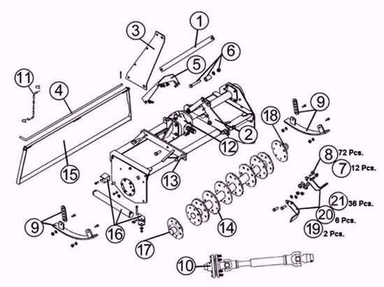
Additionally, familiarizing oneself with the visual arrangement of these elements can assist in the identification and replacement of components. A comprehensive schematic allows users to pinpoint each area accurately, ensuring a better understanding of how maintenance and adjustments should be conducted. This guide aims to empower users with a clear perspective on the tool’s internal and external structures.
Yard Machine Front Tine Tiller Parts Overview
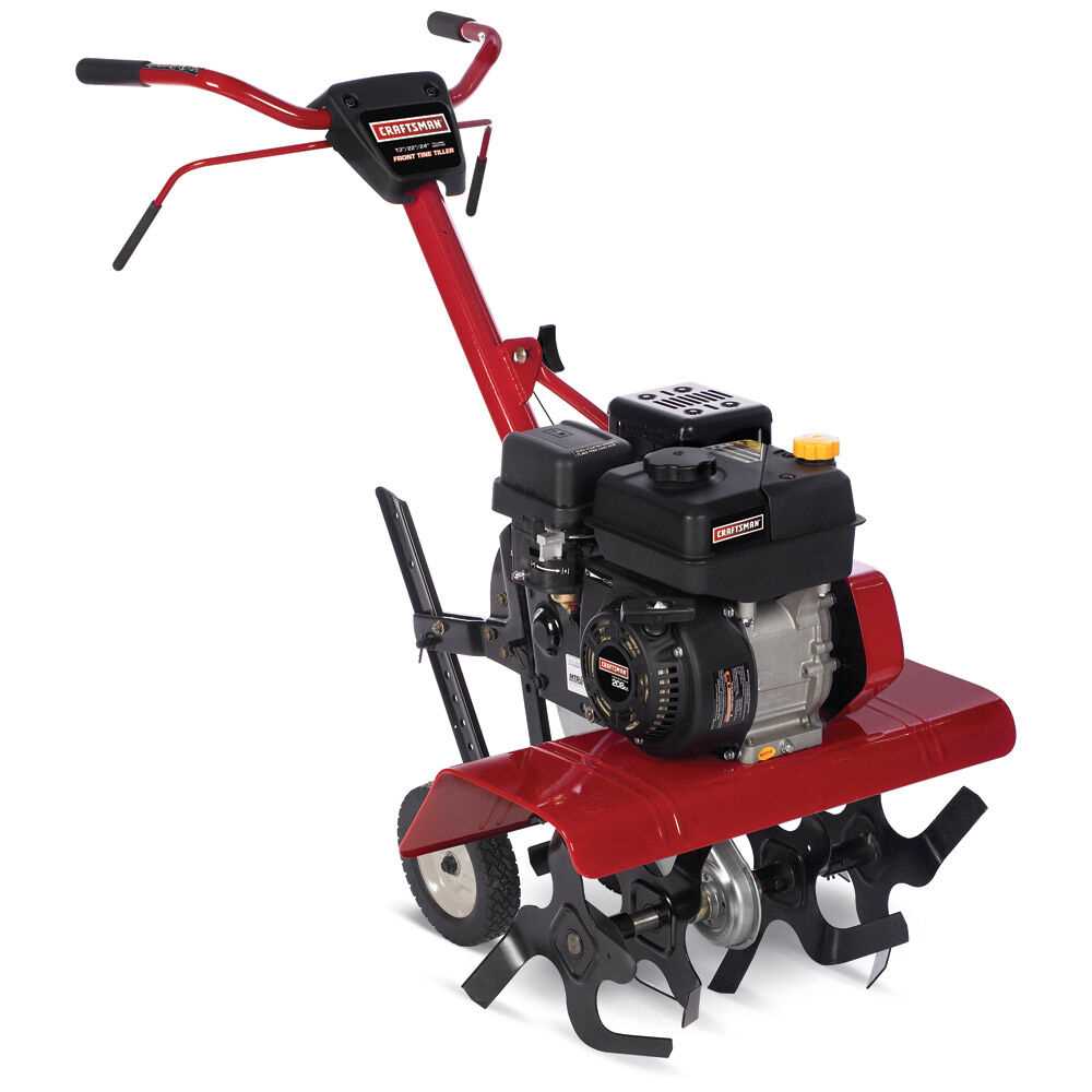
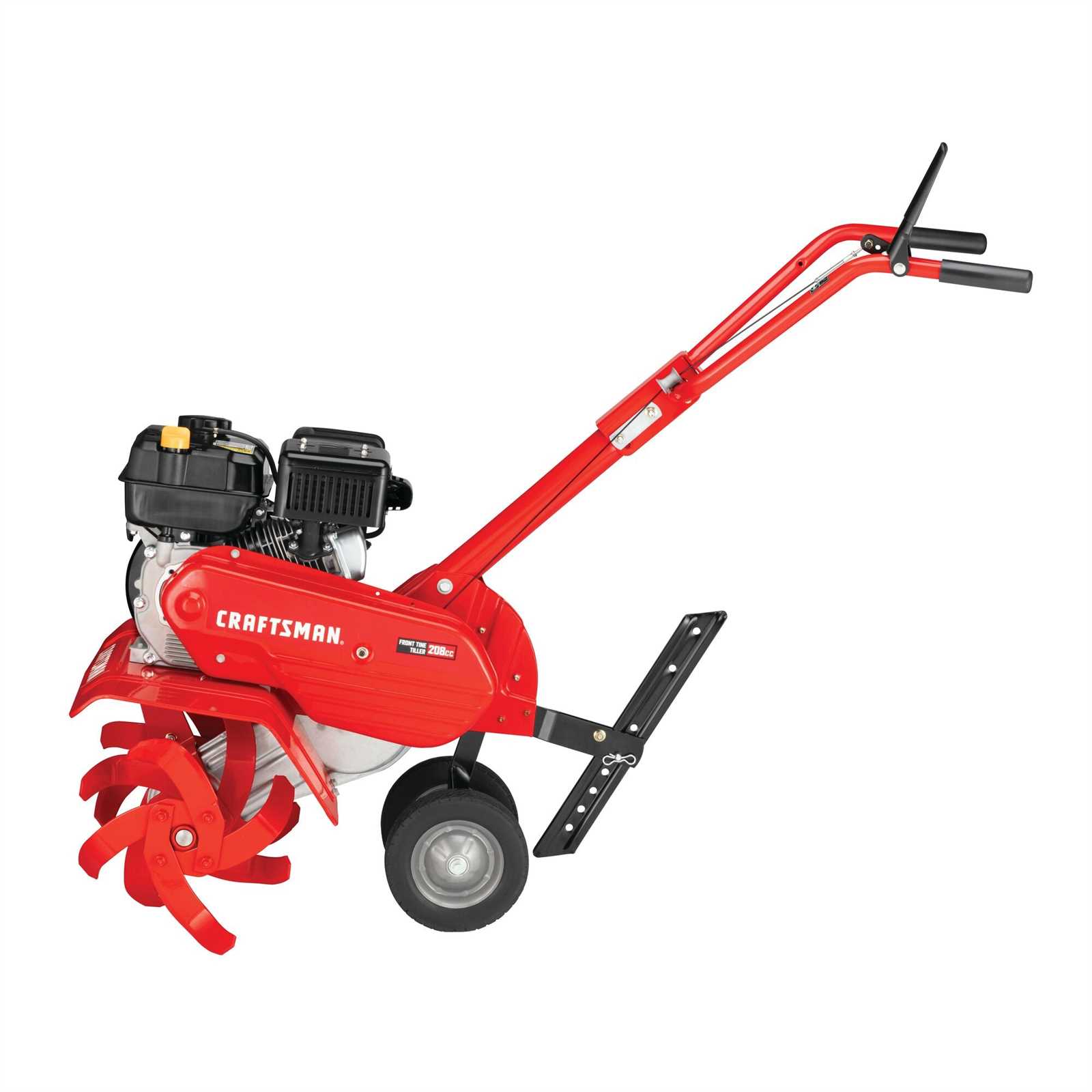
This section provides a comprehensive view of the essential components in a standard soil-cultivating tool. Each element plays a unique role in ensuring smooth operation and effective soil preparation. This overview introduces the main components, emphasizing their purpose and contribution to the entire setup.
| Component | Description |
|---|---|
| Engine Assembly | The core power unit responsible for propelling the tool, allowing for consistent ground engagement and efficient soil turning. |
| Handle Grips | Ergonomically designed for comfortable maneuvering, enabling the operator to maintain steady control over the unit during operation. |
| Drive Belt | A durable belt that transfers power from the engine to the blade system, facilitating steady rotations for effective soil penetration. |
| Blade Set | A set of sharpened, rotating blades designed to break up the ground, ensuring soil aeration and preparation for planting. |
| Depth Adjustment Lever | This lever allows the operator to control the blade depth, enabling customization for various soil conditions and cultivating needs. |
| Wheels | Attached for easy transport and to support stability during operation, especially useful for maneuvering through various terrain types. |
Understanding the Tiller Frame Structure
The framework of a soil preparation tool is essential for both stability and performance. Designed to endure challenging conditions, this structure supports all the key components, ensuring durability and efficient operation.
Below, we’ll explore the major elements of this framework, helping to clarify its purpose and functionality:
- Main Frame: The backbone, connecting various parts and keeping them secure while in use. Built to withstand pressure, it maintains the tool’s balance and control.
- Handlebars: Typically adjustable, they provide the user with control and leverage. Quality handlebars improve maneuverability, reducing strain on the operator.
- Support Brackets: These sections reinforce the main structure, helping distribute weight evenly across the tool. They are crucial in maintaining durability under heavy-duty use.
- Protective Covering: Often attached to safeguard key areas from debris, this cover adds a layer of protection, extending the tool’s lifespan.
Understanding these structural elements helps users appreciate the durability and design that go into crafting a reliable soil preparation tool.
Engine Components and Functions
Understanding the essential elements and roles within an engine allows operators to maintain and optimize performance effectively. Each component contributes to the engine’s smooth operation and durability, supporting various mechanical processes that drive power generation and overall functionality.
Key Engine Elements
- Cylinder: Houses the piston and provides the chamber for fuel combustion. This is central to the engine’s power generation.
- Piston: Moves within the cylinder, driven by combustion, and transfers force to the crankshaft, converting energy into mechanical motion.
- Spark Plug: Ignites the fuel mixture, initiating combustion within the cylinder. This small component is critical for consistent engine start-up and performance.
- Crankshaft: Converts the piston’s vertical motion into rotational movement, ultimately powering the machine’s moving parts.
- Carburetor: Regulates the mix of air and fuel, ensuring efficient combustion. Proper tuning of the carburetor can significantly enhance fuel economy.
Supporting Components

- Fuel Tank: Stores fuel, supplying it to the carburetor as needed. Keeping the fuel tank clean helps avoid clogs and ensures a steady fuel flow.
- Exhaust Valve: Releases gases created during combustion, keeping the cylinder ready for the next cycle. Proper function prevents pressure build-up within the engine.
- Cooling System: Maintains optimal temperature, often using air or liquid to prevent overheating, thereby extending the engine’s lifespan.
Each part is integral to the engine’s performance, and regular maintenance ensures longevity, efficiency, and reliability in operation.
Transmission Mechanism Breakdown
The transmission mechanism is essential for efficiently converting engine power into forward motion. Understanding its design and functionality can help in maintaining smooth operation and identifying potential issues quickly.
Key Components: This mechanism typically consists of gears, a drive belt, and linkage systems that work together to transfer energy. Gears interlock and rotate, controlling the direction and speed of movement, while the drive belt ensures consistent power delivery between parts. Linkages enable accurate transitions between different movement settings.
Common Issues: Regular inspection is necessary to prevent issues such as worn gears, loose linkages, or belt slippage, all of which can disrupt performance. Identifying early signs of wear helps extend the lifespan of the equipment and maintain optimal functionality.
Examining the Drive Belt Assembly
The drive belt assembly plays a crucial role in the operation of various agricultural equipment, facilitating the transfer of power from the engine to the working components. Understanding its function and construction can enhance the maintenance and efficiency of the equipment.
Typically composed of several key elements, the drive belt assembly includes the belt itself, pulleys, and tensioning mechanisms. Maintenance of these components is essential to ensure optimal performance. Regular checks for wear and proper tension can prevent potential breakdowns, allowing for uninterrupted use.
In addition, recognizing signs of wear, such as fraying or cracking of the belt, can aid in early detection of issues. Timely replacement of worn components not only extends the life of the assembly but also improves the overall efficiency of the equipment. Proper understanding and care of the drive belt assembly are vital for effective operation.
Clutch System and Its Role
The clutch system is a crucial component in many agricultural devices, enabling the user to manage power transfer between the engine and the working elements. Its functionality directly influences the performance and efficiency of the equipment during operation.
Functionality Overview
This system serves several essential purposes:
- Power Engagement: It allows for the smooth engagement and disengagement of power, facilitating easy operation.
- Speed Control: Users can adjust the speed of the working components to suit various tasks, enhancing versatility.
- Operational Safety: The design helps prevent damage to the machinery and ensures safe handling during use.
Components of the Clutch System
The clutch system comprises several key elements that work together to achieve its functions:
- Clutch Lever: This is the user-controlled mechanism that engages or disengages the system.
- Friction Discs: These components create the necessary friction to transfer power effectively.
- Pressure Plate: It holds the friction discs in place, ensuring reliable contact when engaged.
- Spring Mechanism: This element provides the necessary tension for proper functioning of the clutch system.
Understanding the clutch system’s design and operation is vital for maintaining efficiency and achieving optimal performance during agricultural tasks.
Tine Assembly and Maintenance Tips
This section provides essential guidance for the assembly and upkeep of the digging components that enhance soil cultivation. Proper handling and regular maintenance of these critical elements ensure optimal performance and longevity, contributing to effective gardening or farming practices.
Assembly Guidelines
When assembling the cultivating attachments, follow these steps to ensure a secure fit:
| Step | Description |
|---|---|
| 1 | Gather all necessary components and tools to facilitate a smooth assembly process. |
| 2 | Align the components accurately according to the manufacturer’s specifications. |
| 3 | Secure the attachments using the appropriate fasteners to prevent any loosening during operation. |
Maintenance Practices
Regular maintenance is crucial to enhance the efficiency and durability of the digging elements:
- Inspect the assembly for wear or damage before each use.
- Clean the components after each session to prevent soil buildup and rust.
- Lubricate moving parts regularly to ensure smooth operation.
- Replace any worn or broken elements promptly to maintain optimal performance.
Handle Controls and Adjustments
In any cultivating equipment, the control mechanisms are essential for optimal functionality and user comfort. These components allow the operator to manipulate various functions, ensuring the device performs efficiently. Understanding how to properly adjust these features can significantly enhance the experience and effectiveness of the equipment.
Types of Controls

The controls typically include levers and grips that regulate the speed and direction of movement. Each control is designed for ease of access, allowing for quick adjustments while operating. Familiarity with these elements is crucial for achieving the desired performance and ensuring a smooth operation.
Making Adjustments
Adjusting the controls involves simple mechanisms that can be modified to suit individual preferences. Operators should routinely check the settings and calibrate them as necessary to accommodate varying soil conditions and user comfort. Regular maintenance of these controls can prevent issues and prolong the lifespan of the equipment.
Fuel System Parts and Care
The fuel delivery mechanism is essential for the proper functioning of outdoor equipment. Understanding its components and maintenance requirements ensures optimal performance and longevity. This section highlights the vital elements of the fuel system and offers guidance on their upkeep.
Key Components
- Fuel Tank: Stores the necessary liquid to power the equipment.
- Fuel Lines: Transfer fuel from the tank to the engine.
- Fuel Filter: Cleans the fuel, preventing contaminants from entering the engine.
- Carburetor: Mixes air and fuel in the correct proportions for combustion.
- Fuel Pump: Moves fuel from the tank to the engine efficiently.
Maintenance Tips
- Regularly check the fuel tank for leaks and damage.
- Inspect fuel lines for cracks or wear; replace if necessary.
- Change the fuel filter according to the manufacturer’s recommendations.
- Keep the carburetor clean to ensure proper air-fuel mixture.
- Monitor the fuel pump for unusual noises that may indicate issues.
By focusing on these elements and following maintenance practices, you can enhance the reliability and efficiency of your equipment, ensuring it operates smoothly for years to come.
Air Filter Housing and Replacement
The air filter enclosure plays a crucial role in ensuring optimal performance of outdoor power equipment. This component is designed to protect the engine by filtering out dust and debris from the air intake, thereby promoting efficient combustion and prolonging the lifespan of the machine. Regular maintenance and timely replacement of this housing are essential to keep the engine running smoothly.
To effectively replace the air filter enclosure, follow these steps:
- Turn off the equipment and disconnect it from any power source.
- Locate the air filter housing, usually positioned near the engine.
- Remove any screws or clips securing the enclosure in place.
- Carefully detach the housing to access the filter inside.
- Inspect the old filter for signs of wear or blockage.
- Install the new filter, ensuring it fits securely in place.
- Reattach the housing and secure it with screws or clips.
Regular inspections of the air filter enclosure can help prevent engine damage and maintain performance. It is advisable to consult the manufacturer’s guidelines for specific replacement intervals and part recommendations.
Common Bolt and Fastener Locations
Understanding the typical placements of screws and connectors in equipment can enhance maintenance and repair processes. Identifying where these components are located is crucial for ensuring proper assembly and function.
Key Areas for Fasteners
Fasteners are generally situated in specific zones that require regular attention. Recognizing these common areas helps in diagnosing issues and performing routine upkeep effectively.
| Location | Purpose |
|---|---|
| Chassis | Secures structural integrity and houses internal components. |
| Engine Mounts | Supports the engine and absorbs vibrations during operation. |
| Handle Assembly | Ensures stability and control while maneuvering the equipment. |
| Gearbox | Connects moving parts and allows for efficient power transfer. |
| Wheels | Facilitates movement and supports the overall weight. |
Maintenance Tips
Regular inspection of these areas is essential for optimal performance. Ensuring that all screws and connectors are tightened can prevent malfunctions and extend the life of the equipment.
Wheels and Axle Specifications
This section provides a comprehensive overview of the essential components that facilitate mobility and stability for the equipment. Understanding these elements is crucial for ensuring optimal performance and longevity.
The wheels are typically crafted from durable materials, designed to withstand varying terrain conditions. Their size and tread pattern play a significant role in traction and maneuverability. It is essential to select wheels that not only fit the overall design but also enhance the operational capabilities.
Equally important is the axle, which serves as the central shaft for rotating the wheels. This component must be robust enough to bear the weight of the equipment while providing smooth rotation. The diameter and material composition of the axle influence both its strength and durability, making these specifications vital for maintaining operational efficiency.
For optimal functionality, both the wheels and axle should be regularly inspected and maintained. This proactive approach can prevent potential issues and extend the lifespan of the equipment, ensuring it operates effectively under various conditions.
Understanding Safety Shield Components
In agricultural tools, safety enclosures play a vital role in protecting users from potential hazards. These protective elements are designed to minimize the risk of injury by shielding moving parts and preventing debris from being ejected during operation. A comprehensive understanding of these components is essential for safe and efficient usage.
Key features of safety enclosures include:
- Material Quality: High-grade materials ensure durability and resistance to wear over time.
- Design Ergonomics: Well-structured shields facilitate easy access while maintaining protection.
- Attachment Mechanisms: Secure fastening systems keep shields in place during operation.
Regular inspection and maintenance of safety enclosures can greatly enhance operational safety. Users should:
- Check for signs of wear or damage regularly.
- Ensure all fasteners are secure before use.
- Clean any debris that may obstruct the protective features.
Understanding the functionality and maintenance of these safety components is crucial for ensuring both personal safety and the longevity of the equipment.