Generac Q55G Parts Diagram Overview
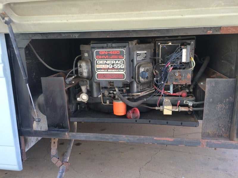
Understanding the internal mechanisms of complex systems can provide valuable insight into how they function and how to maintain them. Each element is designed with precision to serve a specific purpose, contributing to the overall efficiency and reliability of the equipment. Proper knowledge of the components can make troubleshooting and upkeep much easier.
Identifying essential elements is crucial for anyone involved in repair or maintenance. By gaining a detailed view of how each section fits together, users can better understand where potential issues may arise and how to address them effectively. This structured knowledge also aids in enhancing performance through timely servicing and adjustments.
Focusing on individual segments can help users develop a comprehensive understanding of the equipment’s operational flow. Every piece plays a significant role in ensuring the machine runs smoothly and meets its performance expectations. This approach ensures that handling technical issues becomes a more straightforward process.
Overview of Generac Q55G Components
Understanding the essential elements of this power system is key to ensuring reliable performance and longevity. This section provides a breakdown of the key features and structures that make up the unit, highlighting their individual roles and how they function together to deliver consistent power.
Main Sections
Each section within the unit is designed to serve a specific function. These components work in harmony to create a seamless operational experience, ensuring optimal energy delivery in various conditions. Key areas include the power module, control system, and safety mechanisms.
Component Breakdown
Below is a table summarizing the primary components, outlining their purpose and contribution to overall operation:
| Component | Function | |||||||||||||||||||||
|---|---|---|---|---|---|---|---|---|---|---|---|---|---|---|---|---|---|---|---|---|---|---|
| Power Module | Generates and regulates the output for consistent power supply. | |||||||||||||||||||||
| Control System |
| Component | Description |
|---|---|
| Oil Pump | This device circulates lubricant throughout the system, ensuring all necessary parts receive adequate coverage. |
| Oil Filter | Removes contaminants from the lubricant to prevent damage to internal components and maintain efficiency. |
| Oil Reservoir | A storage tank that holds the lubricant until it is needed by the pump for distribution. |
| Lubrication Lines | These pathways carry the oil from the reservoir to various parts of the system, ensuring proper delivery. |
| Pressure Relief Valve | Regulates the pressure within the lubrication system, preventing damage from excessive pressure build-up. |
Starter Motor and Related Parts
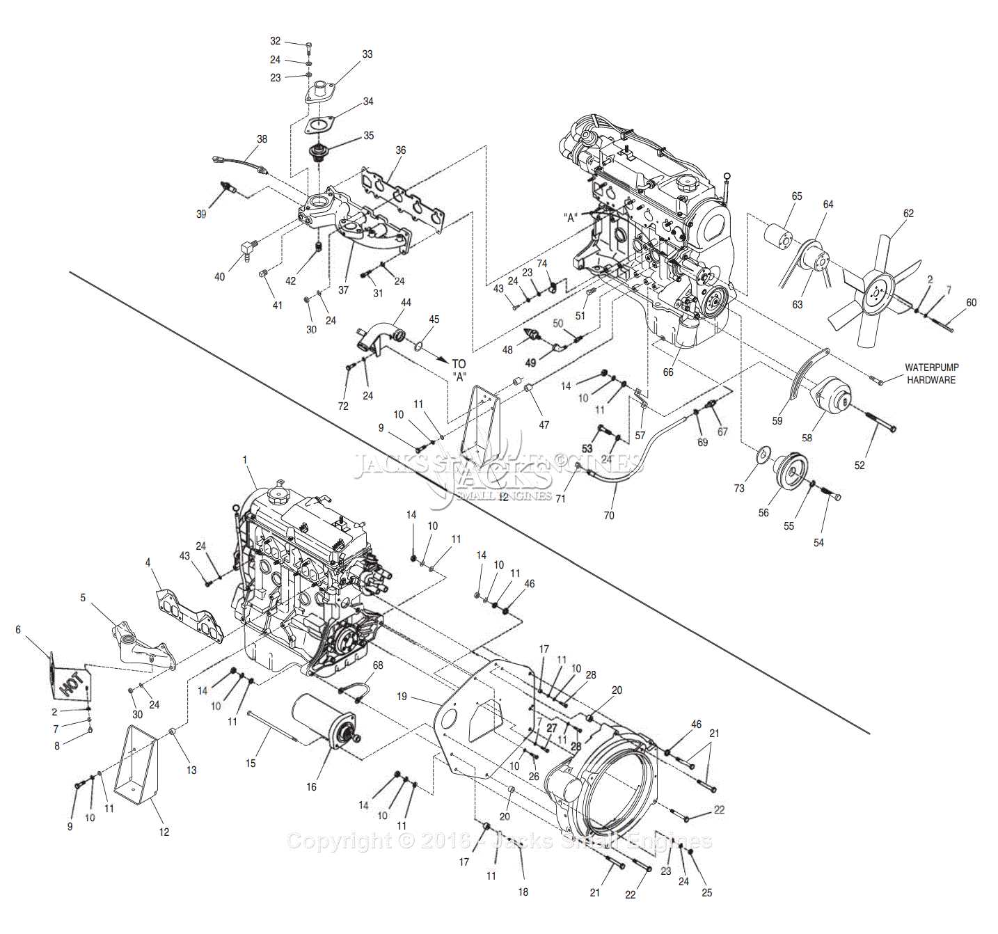
The starter motor is a crucial component in any engine system, responsible for initiating the engine’s operation. Its functionality is essential for providing the necessary torque to start the engine and ensure smooth performance. This section will explore the various elements associated with the starter motor, highlighting their roles and significance in the overall mechanism.
Components of the Starting System
Within the starting system, several key elements work in unison to facilitate the ignition process. These include the battery, which supplies electrical energy, and the ignition switch that activates the starter motor. The solenoid plays a pivotal role in engaging the starter motor with the engine’s flywheel, ensuring a seamless transition from stationary to operational state.
Maintenance and Troubleshooting
Regular maintenance of the starting system is vital to prevent issues that may arise from wear and tear. Inspecting connections and ensuring clean terminals can enhance efficiency. If the engine fails to start, it is essential to examine the battery’s charge, the condition of the ignition switch, and the functionality of the solenoid to identify and rectify potential problems.
Air Filter Housing and Elements
The housing of the air filtration system plays a crucial role in maintaining optimal performance. It serves as a protective enclosure for the filter elements, ensuring that clean air is delivered to the engine while preventing the ingress of contaminants. This component is designed to withstand various environmental conditions, providing durability and reliability.
Within the housing, the filter elements are responsible for trapping dust, dirt, and other particles from the air before it enters the combustion chamber. Regular maintenance and timely replacement of these elements are essential to ensure efficient airflow and prevent engine wear. A well-maintained air filter system contributes to improved fuel efficiency and overall engine longevity.
When inspecting the air filtration system, it is important to check the integrity of the housing for any signs of damage or wear. Ensuring that the filter elements are clean and free from blockages will help in maintaining the performance and efficiency of the engine. Adhering to recommended service intervals will guarantee that the air filtration system functions effectively, safeguarding the engine from potential harm.
Generator Alternator Components
The efficiency and performance of an electrical generator greatly depend on the various components that make up its alternator. Understanding these essential elements can help in maintaining optimal functionality and troubleshooting issues that may arise. The alternator is crucial for converting mechanical energy into electrical energy, and each part plays a specific role in this process.
Key components of an alternator include the rotor, stator, voltage regulator, and rectifier. Each of these parts contributes to the overall operation and reliability of the generator. Below is a table outlining the primary components along with their functions:
| Component | Function |
|---|---|
| Rotor | Creates a magnetic field that induces current in the stator. |
| Stator | Houses the coils that generate electricity when the rotor spins. |
| Voltage Regulator | Maintains the output voltage within a specified range. |
| Rectifier | Converts alternating current (AC) generated in the stator to direct current (DC). |
Battery System and Wiring
The battery system plays a crucial role in the functionality of portable generators, ensuring reliable power delivery during operation. Understanding the components and their interconnections is essential for proper maintenance and troubleshooting.
Battery Components consist of the battery itself, terminals, and wiring harnesses that facilitate electrical flow. Each element must be carefully selected and maintained to optimize performance. The battery serves as the energy reservoir, providing the necessary voltage to initiate the generator’s operation.
Wiring Configuration is equally important, as it connects the battery to the generator’s electrical system. Proper wiring helps to prevent voltage drops and ensures efficient energy transfer. Regular inspection of connections for corrosion or wear can enhance reliability and safety.
In summary, a well-maintained battery system and wiring setup are vital for optimal performance and longevity of the generator. Understanding these components can significantly aid in troubleshooting and ensuring consistent power supply.
Frame and Mounting Parts Diagram
This section provides an overview of the structural components and fastening elements essential for the assembly and stability of the generator unit. Understanding these components is crucial for effective maintenance and troubleshooting, ensuring optimal performance.
Key Structural Components
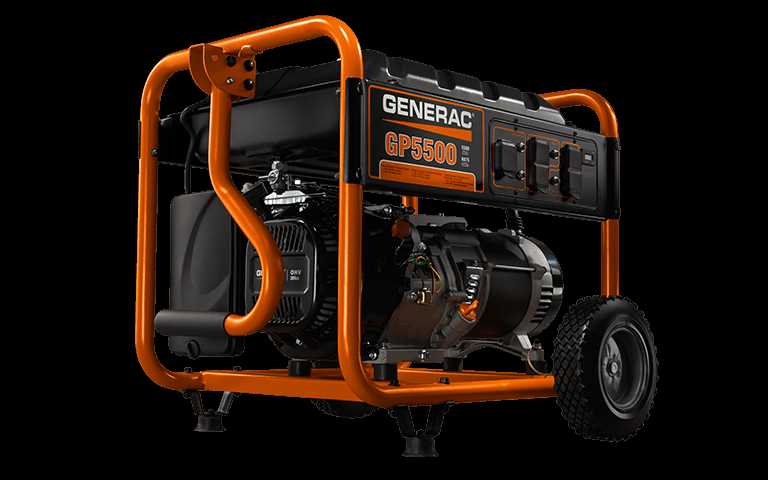
- Base Frame: The foundation that supports the entire system, providing stability and protection.
- Mounting Brackets: These components secure the unit to its base, minimizing vibrations during operation.
- Cross Members: Horizontal supports that enhance the rigidity of the frame, contributing to overall durability.
- Support Legs: Vertical elements that elevate the structure off the ground, promoting air circulation and cooling.
Essential Fastening Elements
- Bolts: Used to connect various parts of the frame securely.
- Nuts: Paired with bolts to ensure a tight fit and prevent loosening over time.
- Washers: Placed between the nut and the frame to distribute load and protect surfaces.
Familiarity with these structural components and fastening elements is vital for assembly, maintenance, and repairs. Regular inspections and replacements can enhance the longevity and reliability of the generator.
