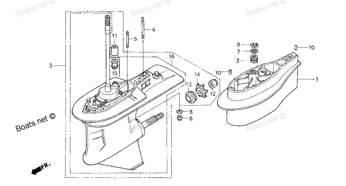
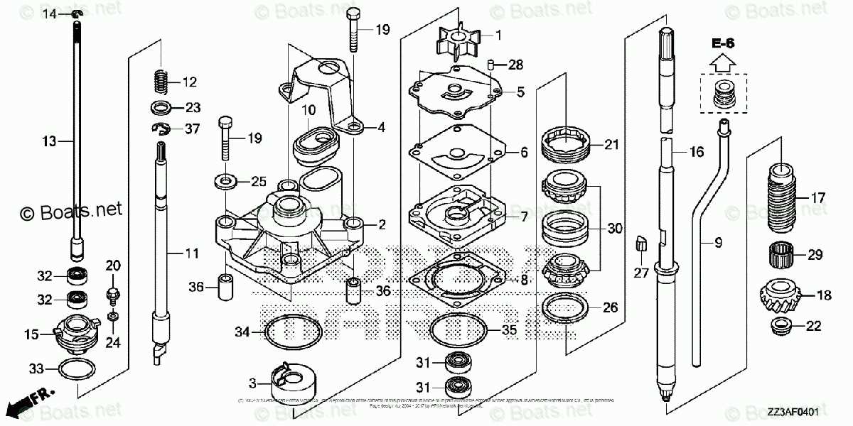
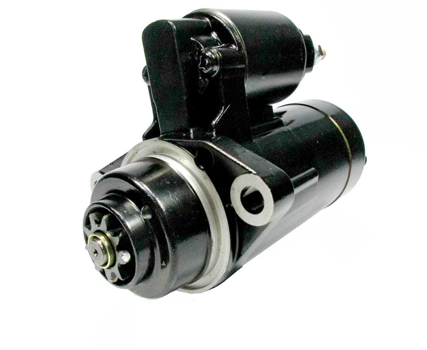
Honda BF90A Parts Diagram

In this section, we delve into the intricate details of the mechanisms that power vessels on the open waters. Our focus shifts towards understanding the internal structure and functionality of critical elements that facilitate propulsion and control.
Visualizing the Internal Configuration
Here, we embark on a journey through the intricate network of components that define the heart of maritime propulsion systems. Each part plays a crucial role in ensuring smooth operation and optimal performance, harmonizing seamlessly to propel boats and ships alike.
Unveiling the Inner Workings
We unveil the inner workings of these essential parts, shedding light on their interconnectivity and the precise roles they play in the broader ecosystem of marine engine dynamics. Understanding these details enhances our appreciation for the engineering marvels that navigate the world’s oceans.
Information about the component layout and structure of the BF90A engine is essential for understanding its assembly and maintenance. This section provides an insightful exploration into the anatomy of the engine’s components and their functional relationships. By delving into the intricacies of its internal makeup, enthusiasts and technicians alike gain a deeper appreciation of its engineering brilliance. Exploring these details enhances the ability to identify and address potential issues, ensuring optimal performance and longevity.
Understanding the Engine Block Components
The engine block serves as the core structure of any internal combustion engine, providing a sturdy foundation for various components to work together seamlessly. Understanding the individual elements within the block is essential for comprehending how the entire system operates. Each component plays a crucial role in facilitating the engine’s performance, contributing to overall efficiency and power generation.
Key Elements of the Engine Block
The primary elements of the engine block include cylinder bores, coolant passages, and oil galleries. Cylinder bores house the pistons, allowing them to move up and down as fuel and air combust. Coolant passages are essential for regulating temperature, preventing overheating by circulating coolant around the engine. Oil galleries ensure proper lubrication of moving parts, reducing friction and wear, which enhances longevity and reliability.
The Importance of Material and Design
The material used in the construction of the engine block is critical, as it must withstand extreme temperatures and pressures. Cast iron and aluminum are common choices, each offering distinct advantages in weight and durability. The design of the block also influences performance characteristics, including displacement and thermal efficiency. A well-engineered block ensures optimal performance, enabling the engine to function smoothly under varying conditions.
Exploring Fuel System Components
The fuel system plays a crucial role in the efficient operation of marine engines, ensuring the delivery of the right amount of fuel for optimal performance. Understanding its various elements is essential for maintaining and troubleshooting the overall functionality.
- Fuel Tank: Stores the fuel and is designed for durability and resistance to corrosion.
- Fuel Pump: Transfers fuel from the tank to the engine, ensuring proper pressure and flow.
- Fuel Filter: Removes impurities from the fuel to protect engine components from damage.
- Fuel Injectors: Atomize fuel for efficient combustion, directly impacting engine performance.
- Fuel Lines: Transport fuel between components, requiring careful inspection for leaks and wear.
By delving into these components, users can gain insights into the overall system and identify potential issues before they escalate.
Analyzing Ignition System Parts

The ignition system is a crucial component in any internal combustion engine, responsible for initiating the combustion process. Understanding the various elements that make up this system is essential for effective maintenance and troubleshooting. Each component plays a specific role in ensuring that the engine operates smoothly and efficiently.
Key Components of the Ignition System
This system typically includes several key elements that work in harmony to deliver a reliable spark. Below are some of the primary components:
| Component | Function |
|---|---|
| Spark Plug | Ignites the air-fuel mixture by creating a spark. |
| Ignition Coil | Transforms low voltage into high voltage to create a spark. |
| Distributor | Distributes the high voltage current to the correct cylinder. |
| Ignition Control Module | Regulates the timing and intensity of the spark. |
Importance of Each Element
Overview of Cooling System Elements
The cooling system in marine engines plays a crucial role in maintaining optimal operating temperatures. It ensures that the engine runs efficiently while preventing overheating, which can lead to severe damage. Understanding the key components of this system is essential for effective maintenance and troubleshooting.
Water Pump: The heart of the cooling mechanism, the water pump circulates coolant throughout the engine. It draws in water from the surrounding environment and pushes it through the cooling passages, helping to dissipate heat effectively.
Thermostat: This component regulates the flow of coolant based on temperature. It opens and closes to maintain a consistent operating temperature, ensuring that the engine warms up quickly and operates within a safe range.
Cooling Passages: These are channels within the engine block that allow coolant to flow and absorb heat. They are designed to maximize surface area contact with hot engine parts, enhancing heat transfer efficiency.
Heat Exchanger: In many systems, a heat exchanger transfers heat from the engine coolant to the surrounding water. This component is vital for cooling the engine while preventing the introduction of contaminants from the external environment.
Hoses and Clamps: These components connect various elements of the cooling system. Hoses must be durable and resistant to wear, while clamps secure them in place, preventing leaks and ensuring proper coolant flow.
Understanding these elements allows for better maintenance practices, helping to prolong the lifespan of the engine and enhance its performance.
Detailing Propeller and Gear Case Parts
This section provides an in-depth look at the essential components that contribute to the efficiency and performance of marine propulsion systems. Understanding each element allows for better maintenance and optimal functionality, ensuring smooth navigation on the water.
Key Components of the Propeller
The propeller plays a crucial role in thrust generation and overall vessel maneuverability. Various elements work together to optimize performance, including the blades, hub, and shaft. Regular inspection and maintenance of these components are vital for preventing performance issues.
Understanding the Gear Case Assembly

The gear case is integral to the transmission of power from the engine to the propeller. It houses vital mechanisms such as gears, bearings, and seals, all of which must be carefully managed to prevent wear and tear. Recognizing the function of each part can significantly enhance durability and reliability.
| Component | Description |
|---|---|
| Blades | Elements that create thrust by converting rotational energy into forward motion. |
| Hub | The central part connecting blades to the shaft, providing stability. |
| Shaft | Transfers power from the engine to the propeller, crucial for movement. |
| Gears | Facilitate the transfer of power and adjust the torque for optimal performance. |
| Bearings | Support moving parts within the gear case, ensuring smooth operation. |
| Seals | Prevent leakage of lubricants and protect internal components from water ingress. |
Examining Electrical System Components
The efficiency and reliability of any engine heavily depend on its electrical system. This system encompasses a variety of crucial components that work in harmony to ensure optimal performance. Understanding these elements is essential for effective maintenance and troubleshooting.
Key Electrical Elements
At the heart of the electrical framework lies the battery, which serves as the primary power source. It stores electrical energy, providing the necessary voltage to initiate the engine and support various accessories. Closely related is the alternator, which generates electricity while the engine is running, replenishing the battery and powering the system.
Wiring and Connections
The wiring harness is another vital aspect, acting as the nervous system that transmits electrical signals throughout the machine. Quality connections are paramount; any corrosion or damage can lead to significant performance issues. Additionally, sensors play a pivotal role in monitoring engine parameters, ensuring that the system operates within designated limits.
Insight into Steering and Control Components
The functionality of marine vessels greatly relies on the efficiency of their steering and control systems. These components ensure smooth navigation and responsive handling, allowing operators to maneuver their craft with precision. Understanding the intricacies of these systems is crucial for maintaining optimal performance and safety on the water.
Key Elements of Steering Mechanisms
At the heart of steering systems lie several critical elements that work in harmony to facilitate direction changes. The helm acts as the primary interface for the operator, translating manual input into mechanical movement. Coupled with a series of linkages and cables, these components transmit force to the rudder or outboard unit, enabling swift and accurate steering. Regular maintenance of these parts is essential to prevent wear and ensure reliable operation.
Control Systems and Their Importance
Control systems encompass various components that govern the vessel’s speed and direction. Throttles and shifters allow for seamless transitions between forward, neutral, and reverse, contributing to the overall maneuverability. Additionally, electronic controls have revolutionized how operators interact with these systems, offering enhanced precision and feedback. Understanding the functionality and upkeep of these systems is vital for a safe and enjoyable boating experience.
Overview of Exhaust System Parts
The exhaust system is a crucial component of any marine engine, responsible for managing the expulsion of gases generated during combustion. Understanding the various elements within this system can enhance maintenance and performance, ensuring the engine operates efficiently and safely.
| Component | Description |
|---|---|
| Exhaust Manifold | Collects exhaust gases from multiple cylinders and directs them to the outlet. |
| Exhaust Pipe | Transports gases from the manifold to the discharge point, often through a series of bends. |
| Water Injection System | Introduces water into the exhaust stream to cool gases and reduce emissions. |
| Silencer/Muffler | Reduces noise produced by the escaping gases, ensuring quieter operation. |
| Exhaust Outlet | The exit point for gases, often located above the waterline to prevent backflow. |
Detailing Power Trim and Tilt Mechanism
The power trim and tilt mechanism is essential for optimizing the performance and maneuverability of marine engines. This system enables precise adjustments of the motor’s angle, enhancing efficiency and control during operation.
Key Components
- Hydraulic cylinder
- Electric motor
- Control switches
- Oil reservoir
Functionality Overview
- The electric motor drives the hydraulic pump.
- Hydraulic fluid is transferred to the cylinder, allowing for adjustment.
- Control switches facilitate operator input for precise tilting.
Understanding these components and their interactions is crucial for maintaining optimal functionality and troubleshooting potential issues.
Analyzing Maintenance Tips for Longevity
Ensuring the durability of machinery requires a thoughtful approach to upkeep. Regular care not only enhances performance but also extends the lifespan of essential components.
- Routine Inspections: Frequently check for wear and tear.
- Cleanliness: Keep surfaces and parts free from debris and contaminants.
- Fluid Checks: Regularly inspect and replace oils and lubricants.
Implementing these strategies can significantly contribute to the ultimate efficiency and reliability of your equipment.
Understanding Parts Replacement Procedures
Effective maintenance of machinery requires a comprehensive understanding of how to replace various components. This process not only ensures optimal performance but also extends the lifespan of the equipment. Familiarity with the necessary steps and tools is crucial for achieving successful replacements without complications.
Preparation and Assessment
Before initiating any replacement, it is essential to assess the current condition of the component in question. Identifying wear and damage will guide the selection of the appropriate replacement part. Make sure to gather all required tools and follow safety protocols to prevent accidents during the process.
Replacement Process
Once the assessment is complete, the next phase involves removing the faulty element. Careful detachment ensures that surrounding components remain unharmed. After removal, installation of the new part should follow the manufacturer’s guidelines closely. Proper alignment and secure fastening are critical to avoid future issues.
Exploring Troubleshooting Techniques
Effective problem-solving in machinery requires a systematic approach to identify and rectify issues. This section delves into various strategies that can be employed to diagnose faults, ensuring optimal performance and longevity of equipment.
Common Techniques
One of the most useful techniques is the process of elimination, where potential causes are methodically ruled out. Additionally, visual inspections can reveal wear and tear that might not be immediately apparent.
Recording Symptoms
Documenting any irregular behavior aids in identifying patterns over time. Keeping detailed records can help pinpoint recurring issues and streamline the troubleshooting process.
| Technique | Description |
|---|---|
| Visual Inspection | Examine components for signs of damage or wear. |
| Process of Elimination | Rule out potential causes step by step. |
| Documenting Symptoms | Keep track of issues and their frequency for better analysis. |