Kawasaki FR691V Parts Diagram Guide
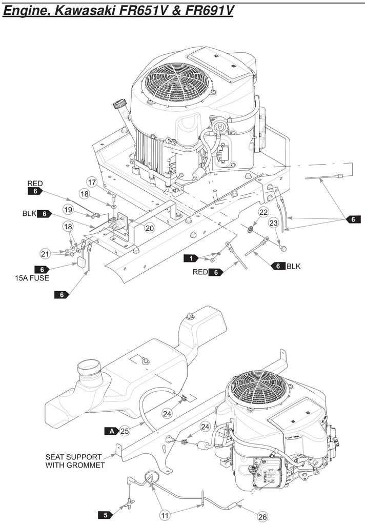
When it comes to understanding a mechanical system, it’s crucial to have a comprehensive view of its layout and individual components. This allows for better maintenance, efficient troubleshooting, and overall improved longevity. For enthusiasts and professionals alike, grasping the specific arrangement of each element can transform the way one approaches repairs and upgrades.
In this guide, we’ll delve into the various aspects of a robust engine model, examining each part’s function and how they interconnect to deliver dependable power. With a focus on optimizing performance, this overview provides an in-depth look at the arrangement and purpose of each key section, helping users keep their equipment in top condition.
Whether you’re looking to conduct regular upkeep or carry out more detailed fixes, having a clear understanding of the layout and design is indispensable. We’ll highlight the main features and offer insights into how each section works together, ensuring your setup operates at peak efficiency and lasts for years to come.
Engine Component Overview
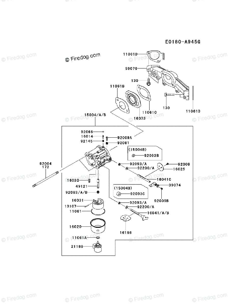
This section provides an insight into the major elements that make up this robust engine. Designed for optimal performance, it combines durability and efficiency, with each part contributing to the system’s overall reliability and power output. Understanding the key components helps in better appreciating the intricate workings of this engine model and aids in routine maintenance and troubleshooting.
Core Mechanical Components
The engine houses a series of essential mechanical parts that work in unison to deliver smooth and consistent operation. At the heart of the system, the crankshaft transforms the energy produced into rotational force, enabling movement. Cylinders play a crucial role in generating power by allowing for controlled combustion, while pistons move within them, converting pressure into motion. Supporting this process, the camshaft ensures precise timing of the intake and exhaust valves, maximizing efficiency and performance.
Cooling and Lubrication Systems
To maintain optimal temperatures, this engine employs a reliable cooling system that prevents overheating. Air is directed over the cooling fins, dissipating excess heat generated during operation. In addition, a well-designed lubrication system ensures that all moving parts are adequately oiled, reducing friction and wear over time. By keeping the engine’s temperature under control and components well-lubricated, these systems play a vital role in extending its lifespan and maintaining its
Main Features of the Efficient V-Twin Engine

This reliable V-twin power source is known for its impressive performance, fuel efficiency, and durability. Designed to handle demanding tasks with ease, it provides a consistent power output, making it a preferred choice for a variety of applications. This engine combines efficiency with long-lasting operation, allowing users to achieve the best results with minimal maintenance.
High-Performance Design
The engine’s V-twin configuration delivers smooth operation, reducing vibrations and enhancing overall comfort. Its overhead valve (OHV) design increases efficiency by promoting cooler operation and better fuel economy. Additionally, the well-balanced build ensures quieter running, creating a more pleasant experience for users.
Durability and Ease of Maintenance
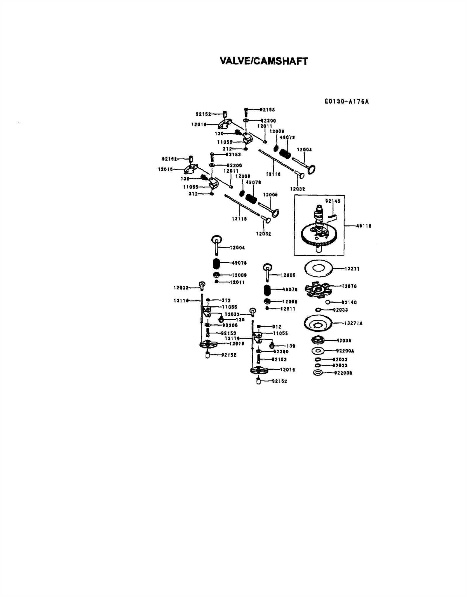
Crafted for longevity, this engine includes features such as a heavy-duty air filter and durable cylinder heads that protect internal components from wear. Maintenance is straightforward, thanks to accessible components that make routine checks and servicing quick and efficient. These features contribute to a prolonged engine lifespan, even in challenging conditions.
Reliable ignition systems, coupled with high-quality lubrication mechanisms, further enhance this engine’s ability to perform consistently. From heavy workloads to everyday tasks, this power source is designed to meet diverse needs with robust performance.
Understanding the Cooling System Layout
The cooling mechanism is designed to maintain optimal engine temperatures, ensuring steady performance and longevity. This system efficiently dissipates heat produced during operation, which is crucial for preventing potential overheating and subsequent damage. Comprising multiple components, each part plays a unique role in keeping the engine cool and functional under varying conditions.
Main Components of the Cooling System
At the core of the cooling setup, the fan and radiator work in tandem to circulate air and dissipate heat away from the engine. The fan directs airflow across the radiator’s surface, where heat is exchanged and reduced. In combination, these elements are responsible for managing temperature levels, especially in intense operating scenarios.
Supporting Elements and Their Functions
Several other components assist in the cooling process. The shroud around the fan enhances airflow direction, maximizing efficiency. Additionally, the fins on the radiator provide a greater surface area for heat exchange, allowing the cooling mechanism to work effectively even during prolonged use. Together, these supporting parts ensure the system runs smoothly, safeguarding the engine’s performance.
Air Filter System Parts and Function
The air filtration system is crucial for maintaining the performance and longevity of an engine. By preventing debris and dust from entering, it protects the internal components from wear and damage. This system ensures that only clean air mixes with fuel, contributing to efficient combustion and overall engine health.
Main Components of the Filtration System
The air filtration setup is made up of various elements that work together to deliver purified air to the engine. Each part has a unique role in achieving this goal. Below is a breakdown of the key components:
| Component | Function | ||||||||||||||||||
|---|---|---|---|---|---|---|---|---|---|---|---|---|---|---|---|---|---|---|---|
| Filter Housing | Encases the filter and provides a stable structure, keeping the filter protected from external impacts and contaminants. | ||||||||||||||||||
| Air Intake Duct | Channels air from outside the engine area into the filter housing, where it can be purified before entering the engine. | ||||||||||||||||||
| Filter Element | The core of the system, this part is responsible for capturing dust, pollen,
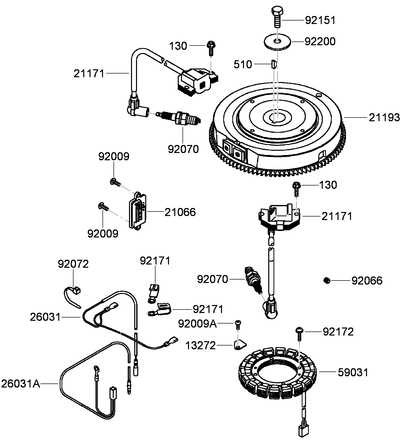
Ignition System Components ExplainedThe ignition system is crucial for starting and maintaining the operation of any engine. This system is designed to ignite the air-fuel mixture within the engine’s combustion chamber, enabling efficient power generation. By understanding each component’s role, you can gain insight into how they work together to deliver reliable and consistent performance. Spark Plug: The spark plug plays a vital role in delivering the spark necessary to ignite the fuel mixture. It’s positioned in the combustion chamber, where it uses an electrical current to produce a spark that initiates the engine’s power cycle. A properly functioning spark plug ensures a smooth start and efficient operation. Ignition Coil: This component amplifies the voltage from the battery and sends it to the spark plug. It converts low voltage into high voltage, which is essential for creating a strong spark. The ignition coil is often designed to work in sync with the spark plug, ensuring that the right amount of energy is delivered at the right time. Flywheel: The flywheel is equipped with magnets that interact with the ignition co Examining the Fuel Pump MechanismThe fuel delivery system is vital for optimal engine performance, ensuring that the power unit receives the necessary fuel to operate efficiently. Understanding the workings of the fuel pump mechanism is essential for maintenance and troubleshooting. This section delves into the components and functions of this critical system. Key Components of the Fuel Pump
Functionality of the Fuel PumpThe fuel pump operates by drawing fuel from the storage tank and pushing it through the filter into the engine’s intake system. This process involves:
Regular inspection and maintenance of the fuel pump and associated components are crucial to prevent fuel delivery issues and ensure long-lasting engine performance. Throttle Linkage and Carburetor Assembly
The throttle linkage and carburetor assembly play crucial roles in the performance and efficiency of small engines. These components work in tandem to regulate the airflow and fuel mixture that reaches the engine, directly impacting its operation. Understanding their structure and functionality is essential for effective maintenance and troubleshooting. Components OverviewThe primary elements involved in the throttle linkage and carburetor assembly include:
Assembly and AdjustmentProper assembly and adjustment of the throttle linkage and carburetor are vital for smooth engine operation. Key steps include:
Oil Filter and Lubrication System OverviewThe efficient operation of any engine relies heavily on a well-designed lubrication mechanism. This system plays a crucial role in reducing friction between moving components, ensuring optimal performance and longevity. By circulating oil throughout the engine, it not only lubricates but also helps in dissipating heat, thereby maintaining the engine’s overall temperature within safe limits. The oil filter is an integral component of this system, tasked with removing contaminants from the lubricating fluid. By trapping dirt, debris, and metallic particles, the filter helps maintain the purity of the oil, which is vital for the smooth functioning of the engine. Regular replacement of the filter is essential to ensure it operates effectively and does not become a blockage in the oil flow. Additionally, the lubrication system is designed to ensure that the oil reaches all necessary areas of the engine, including bearings, gears, and other friction-prone components. This continuous flow of oil not only prevents wear and tear but also enhances efficiency by minimizing energy loss due to friction. Proper maintenance of both the filter and lubrication system is essential for sustaining the performance and durability of the engine. Detailed View of the Cylinder HeadThe cylinder head is a critical component in an internal combustion engine, playing a vital role in the engine’s performance and efficiency. It serves as a barrier between the engine’s cylinders and the outside environment, housing essential parts that facilitate the intake and exhaust processes. A thorough understanding of this component can greatly assist in troubleshooting and maintenance tasks. This section explores the various elements that constitute the cylinder head, highlighting their functions and interactions within the engine system.
Understanding these components and their respective roles enhances the knowledge necessary for effective maintenance and repair. Regular inspections and timely replacements can significantly extend the lifespan of the engine and improve overall performance. Electrical Wiring and Battery ConnectionsThe effective management of electrical systems is crucial for ensuring optimal performance in outdoor power equipment. Proper wiring and secure battery connections not only enhance functionality but also contribute to the longevity of the machinery. This section will explore the essential components involved in electrical configurations and how to maintain reliable power sources. Understanding Wiring LayoutsEach electrical system consists of a series of interconnected components that facilitate the flow of electricity. Wires must be carefully routed to minimize interference and prevent potential hazards. Utilizing appropriate gauges and insulation materials is vital to maintaining safety and efficiency. Regular inspection of connections and securing points can help in identifying wear or damage that could lead to failures. Battery Installation and Maintenance
Securing a reliable power source begins with the proper installation of the battery. Ensuring that terminals are clean and free of corrosion is essential for optimal conductivity. It is advisable to use protective covers for terminals to prevent accidental short circuits. Regularly checking the electrolyte levels and ensuring that the battery is firmly secured within its compartment can greatly extend its lifespan. Always follow the manufacturer’s guidelines for voltage requirements and specifications to avoid complications. In conclusion, a thorough understanding of wiring systems and battery management is paramount for maintaining efficiency and safety in outdoor power machinery. Routine maintenance and attention to detail can prevent operational issues and enhance overall performance. Exhaust System Parts and Configuration
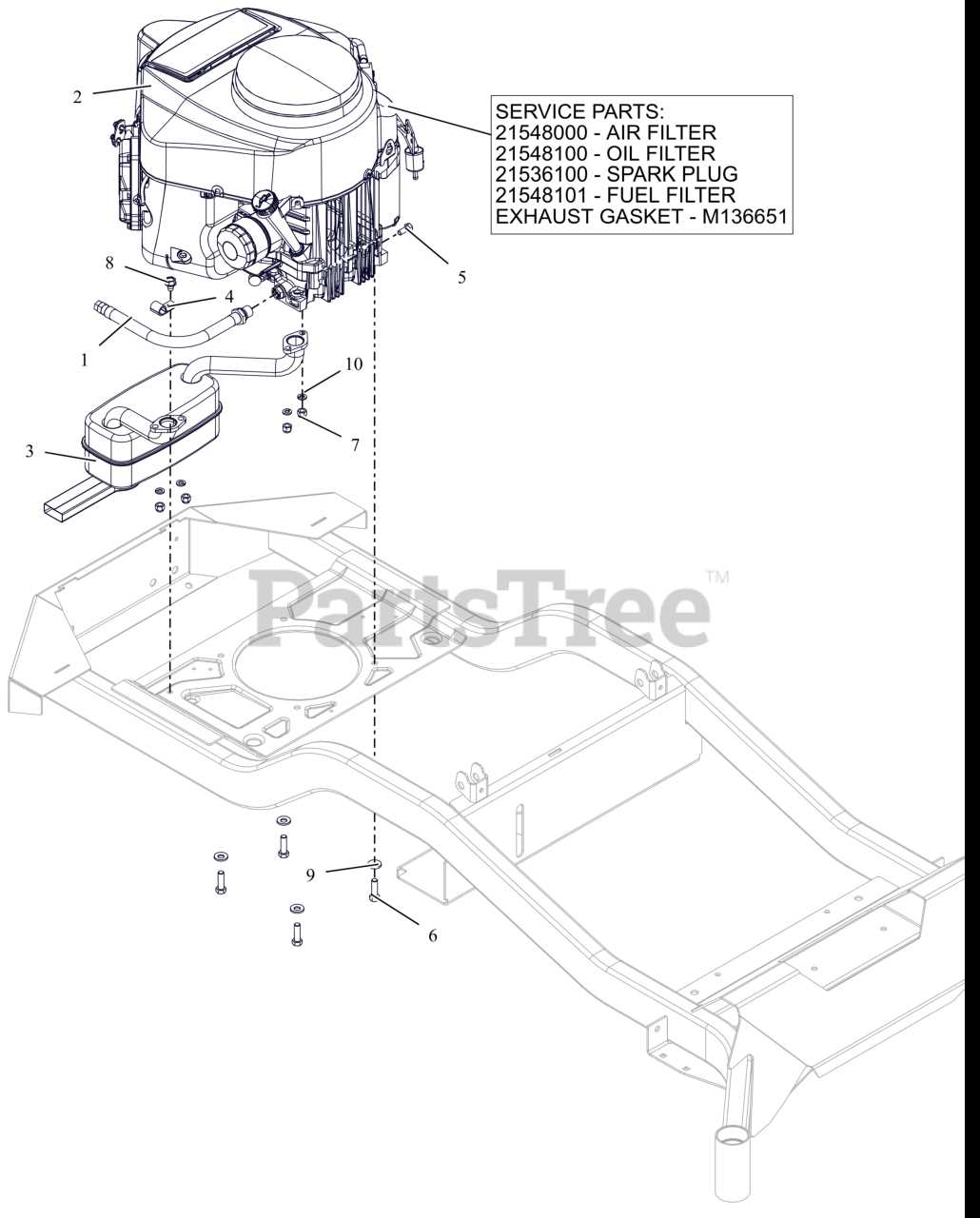
The exhaust assembly plays a vital role in the overall efficiency and performance of a small engine. Understanding its components and layout is essential for proper maintenance and optimization. This section delves into the various elements that constitute the exhaust framework, outlining their functions and interrelationships. Key Components of the Exhaust Assembly
Configuration ConsiderationsWhen configuring the exhaust system, several factors must be considered to ensure optimal performance:
Maintenance Tips for Kawasaki FR691V PartsRegular upkeep of your equipment components is essential for ensuring optimal performance and longevity. By following a few simple guidelines, you can maintain the functionality and efficiency of your machinery, preventing potential issues before they arise. Routine InspectionsConducting frequent checks of your equipment allows you to identify wear and tear early on. Look for any signs of damage, such as cracks or fraying. Pay close attention to the key components, ensuring they are secure and operating smoothly. If you notice any irregularities, address them promptly to avoid further complications. Proper LubricationEnsuring that moving parts are adequately lubricated is crucial for reducing friction and wear. Use the manufacturer-recommended lubricants, applying them as specified in the user manual. Regularly clean the areas around lubrication points to prevent debris from contaminating the lubricants. In summary, consistent maintenance routines will enhance the durability and performance of your machinery. By incorporating these tips, you can extend the lifespan of your equipment and enjoy reliable operation for years to come. |
