| Gears |
Hydraulic Circuit Diagram
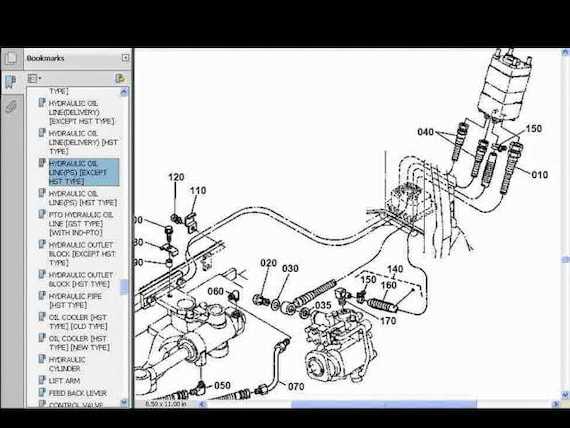
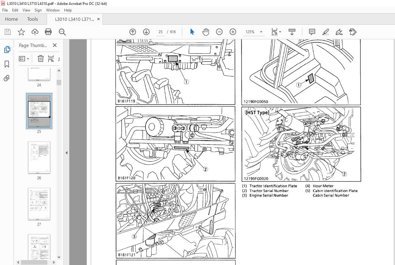
The hydraulic system plays a crucial role in ensuring smooth operation by transferring energy through fluid power. Understanding the layout of this system is essential for proper maintenance and troubleshooting. The flow of hydraulic fluid, pressure regulation, and the interaction between different components must be carefully considered to keep the system efficient and functional.
Key Components
The hydraulic circuit typically consists of a pump, valves, actuators, and hoses that direct the fluid under pressure. Each of these parts works together to control the movement of various machinery elements, ensuring precise operation and response.
Fluid Flow Path
The movement of hydraulic
Electrical Wiring Schematic
The electrical wiring schematic is essential for understanding how the various electrical components in a system are interconnected. It provides a clear overview of the wiring paths, helping to identify connections, potential issues, and ensuring proper installation or repair work. A well-organized schematic simplifies the process of troubleshooting electrical faults.
Key Components and Connections
This section outlines the
Cooling System Parts Layout
The layout of the cooling system is essential for maintaining optimal engine performance. This section outlines the various components involved in regulating temperature and ensuring efficient operation. A well-designed cooling mechanism prevents overheating and extends the lifespan of the machinery.
Key Components of the Cooling System
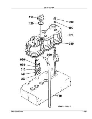
Several vital elements work together to facilitate effective cooling:
- Radiator: This component dissipates heat from the coolant, allowing it to return to a lower temperature.
- Water Pump: The pump circulates coolant throughout the engine and the radiator.
- Thermostat: It regulates the flow of coolant based on the engine’s temperature, maintaining optimal operating conditions.
Importance of Proper Maintenance
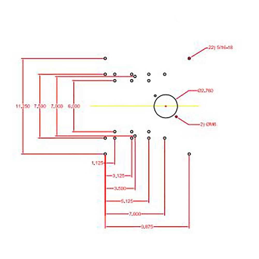
Regular maintenance of the cooling system is crucial for preventing potential issues. Checking coolant levels, inspecting hoses, and ensuring the radiator is free of debris are essential steps to ensure longevity and efficiency.
Fuel System Components
The fuel system in machinery plays a crucial role in ensuring efficient engine performance. It comprises various elements that work together to store, filter, and deliver fuel to the engine, optimizing combustion and overall functionality.
Key components of the fuel system include:
- Fuel Tank: This reservoir holds the fuel, providing a steady supply to the engine.
- Fuel Pump: This component transports fuel from the tank to the engine, ensuring adequate pressure for proper operation.
- Fuel Filter: Essential for maintaining engine health, the filter removes impurities and contaminants from the fuel before it reaches the engine.
- Injectors: These devices atomize the fuel, delivering it into the combustion chamber at the right time and quantity for optimal combustion.
- Fuel Lines: These pipes carry fuel between the tank, pump, filter, and injectors, designed to withstand the pressures of the fuel system.
Each of these components is vital for the effective functioning of the fuel system, contributing to the overall efficiency and reliability of the engine.
Front and Rear Axle Details
The axles play a crucial role in the overall functionality and performance of a vehicle, providing stability and support for the weight distribution. Understanding the components and mechanisms of both the front and rear axles is essential for effective maintenance and troubleshooting.
Components of the Axles
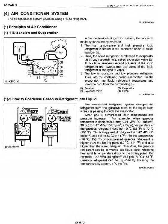
Each axle consists of various parts that work together to ensure smooth operation. The main components include:
- Housing: The main structure that supports the axle.
- Bearings: Allow smooth rotation and reduce friction.
- Shaft: Transfers power from the engine to the wheels.
- Universal Joints: Facilitate movement and flexibility between connected parts.
Maintenance Tips
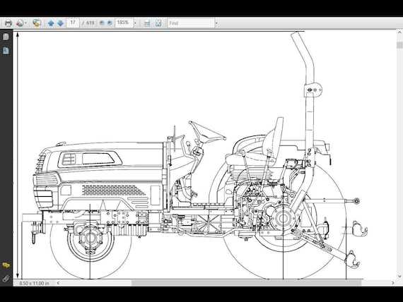
Regular maintenance of the axles can prevent major issues. Here are some key practices:
- Inspect the axle housing for any signs of damage or wear.
- Check the fluid levels and quality in the axle assemblies.
- Lubricate bearings regularly to minimize friction.
- Monitor tire alignment to ensure even weight distribution.
Steering Mechanism Configuration

The steering system of agricultural machinery plays a crucial role in ensuring precise maneuverability and control. This configuration consists of various components that work together to facilitate smooth navigation across diverse terrains. Understanding the arrangement and function of these elements is essential for maintaining optimal performance.
Key components include the steering wheel, which acts as the primary control interface for the operator, and the steering linkage, responsible for transmitting the driver’s inputs to the wheels. By effectively managing these elements, the vehicle can achieve responsive handling and stability during operation.
Regular inspection of the steering mechanism is vital to identify any wear or misalignment that could impact functionality. Ensuring proper adjustments and timely replacements of worn-out parts enhances the overall reliability of the steering system, contributing to safer and more efficient use of the machinery.
Brake System Assembly
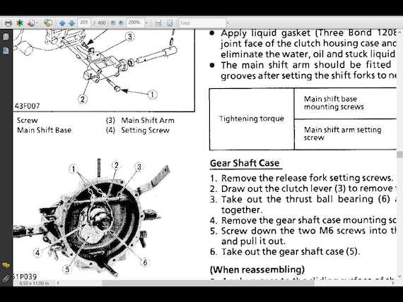
The brake system assembly is a crucial component designed to ensure effective stopping power and safety during operation. This assembly consists of various elements that work together to provide reliable braking performance. Understanding the arrangement and functionality of these parts is essential for maintaining optimal performance and ensuring the longevity of the equipment.
Components Overview
This section will highlight the key components involved in the brake system assembly, including their roles and interconnections. Familiarity with these parts is vital for troubleshooting and repairs.
| Component |
Description |
| Brake Pedal |
Controls the application of braking force. |
| Master Cylinder |
Generates hydraulic pressure to activate the brakes. |
| Brake Lines |
Transmits hydraulic fluid between components. |
| Brake Caliper |
Houses the brake pads and applies friction to the brake discs. |
| Brake Pads |
Friction material that presses against the disc to slow down the vehicle. |
| Brake Disc |
Rotating component that works with brake pads to slow the machine. |
Maintenance Tips
Regular inspection and maintenance of the brake system assembly are essential for safe operation. It is advisable to check the hydraulic fluid levels, inspect brake pads for wear, and ensure all connections are secure to prevent failures.
Maintenance Parts and Filters
Ensuring the proper upkeep of your equipment requires regular attention to key components that help maintain optimal performance. Regular checks and replacements of essential items like filters are crucial for longevity and smooth operation.
Essential Components for Maintenance
Several critical elements need regular inspection and potential replacement to keep your machine running smoothly. Here are the most important items to keep track of:
- Engine oil filters
- Fuel filters
- Air filters
- Hydraulic fluid filters
Replacing Filters
Replacing filters is one of the most straightforward yet essential tasks in equipment maintenance. Below is a list of typical filter replacement intervals:
- Oil filters: Every 100 hours of operation
- Fuel filters: Every 200 hours of operation
- Air filters: Every 250 hours
Safety Features and Controls Diagram
This section provides an overview of the essential safety mechanisms and operational controls present in machinery. Understanding these elements is crucial for ensuring safe usage and maintenance. By familiarizing oneself with these components, operators can enhance both their safety and the longevity of the equipment.
Key Safety Mechanisms
Safety mechanisms are designed to prevent accidents and injuries during operation. These features include emergency shut-off switches, protective guards, and automatic shut-off systems that activate under specific conditions. Regular checks and maintenance of these components are vital for optimal performance.
Control Layout and Functionality
The layout of operational controls is strategically designed for user accessibility and efficiency. Operators should be aware of the functions of each control, including throttle adjustments, steering mechanisms, and braking systems. Proper training in using these controls significantly enhances operational safety and effectiveness.
