Yard Machine Tiller Parts Diagram Guide
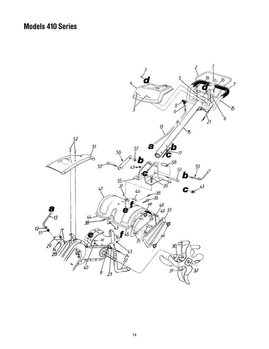
Understanding how different elements of equipment are organized is crucial for efficient maintenance and repair. This guide aims to provide detailed insights into the arrangement and connection of various components in gardening tools, helping users optimize their performance and longevity.
Visual representations of mechanical systems offer a clear and concise way to grasp the relationship between different mechanisms. Whether you’re looking to replace a specific element or understand how different parts work together, having a well-structured layout overview can make the task easier and more efficient.
By exploring the structural organization, users can save time, ensure compatibility when ordering replacements, and gain confidence in performing repairs themselves. This article will help you navigate through these complex systems and ensure smooth operation of your equipment.
Understanding Yard Machine Tiller Components
Recognizing the individual components of soil-cultivating equipment is essential for proper maintenance and effective operation. Each part has a specific role that contributes to the overall performance, ensuring efficient soil preparation for planting. By learning the key elements of this equipment, users can diagnose issues, perform repairs, and maintain optimal functionality.
Blades and Tines: These cutting and turning elements break up the soil, enabling better aeration and nutrient distribution. Well-maintained blades ensure smooth and consistent performance, while worn-out ones may hinder progress.
Transmission System: The drive mechanism transfers power from the motor to the rotating elements, allowing for efficient soil manipulation. Proper upkeep of this system ensures smooth operation and prevents mechanical failure.
Handle and Control Panel: These provide the operator with control over speed, direction, and depth settings. A comfortable and responsive handle system allows for easy maneuvering, ensuring precise control during operation.
Exploring the Engine Structure and Design
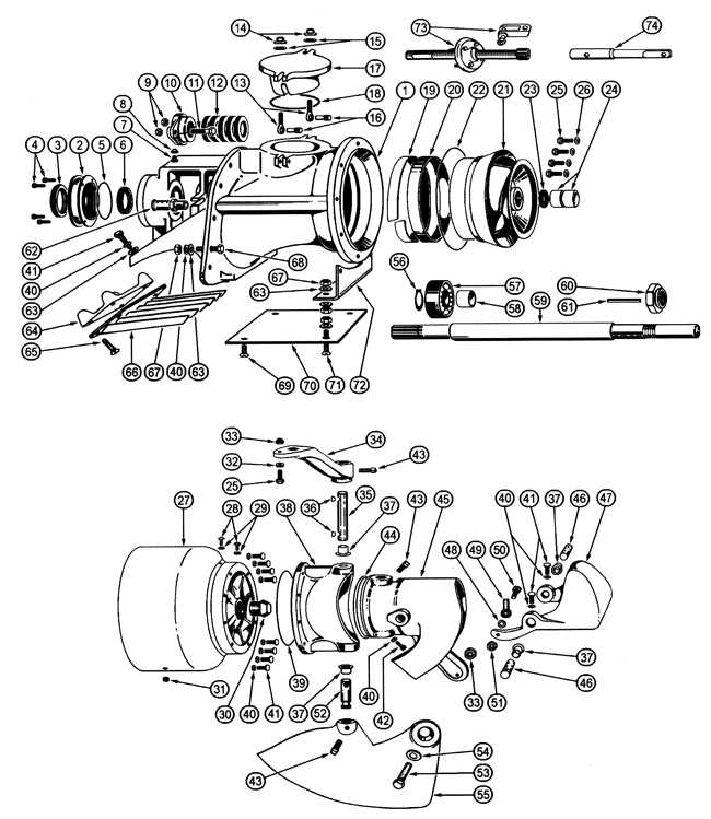
The internal workings of an engine rely on a complex network of components working in harmony to deliver power efficiently. Understanding how these elements are assembled and how they interact can give valuable insight into the performance and durability of the entire system. Each part plays a critical role in maintaining the engine’s functionality, from fuel intake to mechanical movement.
Key elements such as the combustion chamber, crankshaft, and piston operate with precision to convert fuel into kinetic energy. The design of these components, along with their alignment and synchronization, ensures smooth and reliable operation, optimizing the power output.
By examining the structural layout of the engine, we can observe how airflow, heat management, and fuel efficiency are all optimized. This balance of design and functionality directly influences both performance and longevity.
Identifying Essential Parts for Maintenance
Regular upkeep of any mechanical equipment ensures its smooth operation and longevity. A key aspect of this is recognizing the fundamental components that require consistent attention. Understanding how to inspect and maintain these critical elements can prevent potential issues and extend the lifespan of the equipment.
Below are the most crucial areas to focus on during routine checks:
- Drive Mechanism – This component is responsible for powering the unit. Regular lubrication and inspection can prevent wear and tear.
- Blades or Tines – Keeping these sharp and free of debris ensures effective performance. Checking for damage or dullness is essential.
- Control Cables – Ensure that cables are free of fraying or damage to maintain proper functionality.
- Transmission – This area should be inspected for smooth operation and any signs of leakage or wear.
- Fasteners and Bolts – Regularly tightening loose bolts and fasteners helps preve
How to Replace Worn-Out Belts
Over time, belts in various equipment can become worn or damaged, leading to decreased performance. Replacing these belts is an essential part of maintenance that ensures smooth operation and longevity of your tools. In this guide, we will walk through the steps to identify and replace a belt that has seen better days, helping to restore efficiency and functionality.
Identifying a Damaged Belt
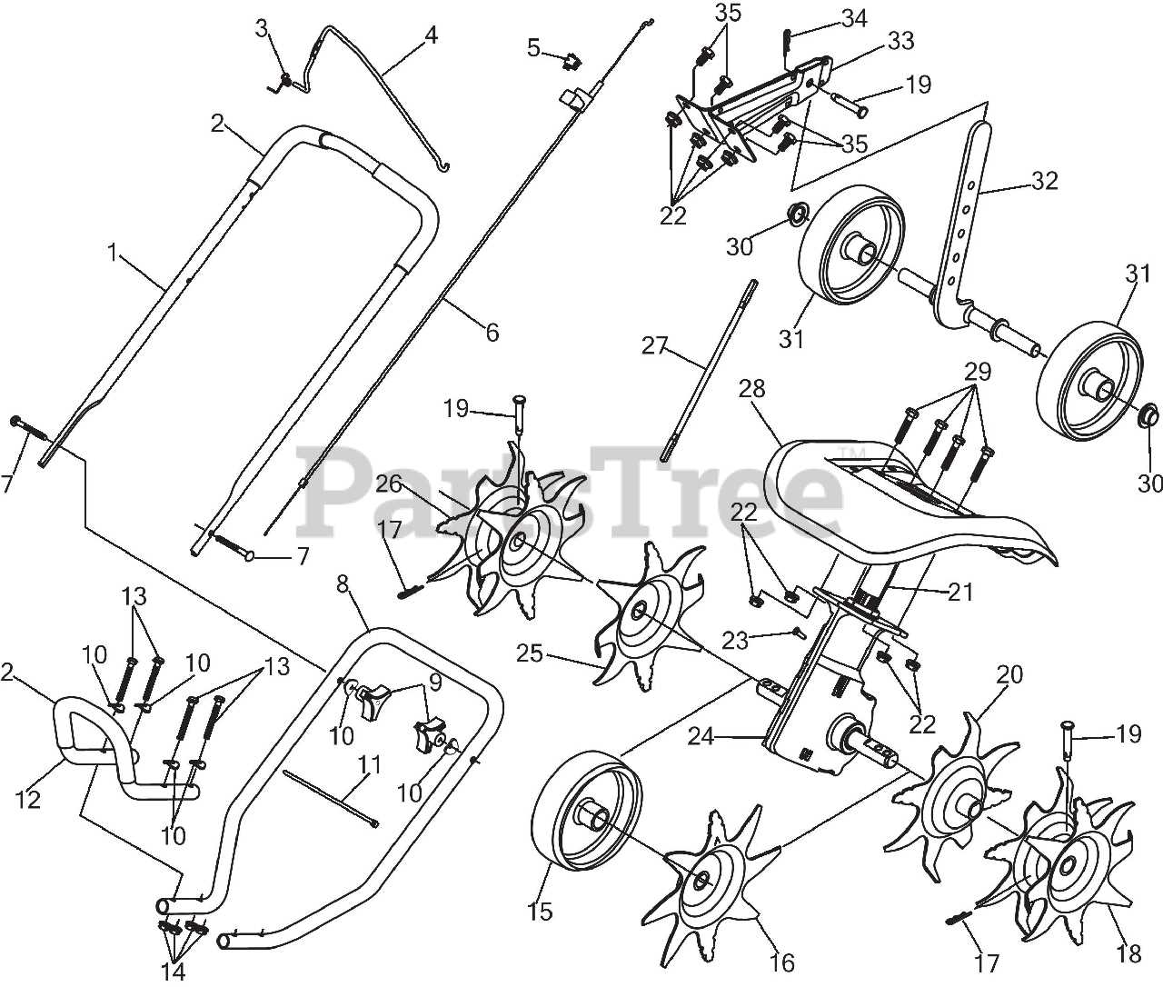
Before beginning the replacement process, it’s crucial to recognize the signs of a deteriorating belt. Look for cracks, fraying, or stretching that could indicate the belt is no longer in optimal condition. If any of these symptoms are present, it’s time for a replacement.
Steps for Replacing the Belt
First, ensure that the equipment is turned off and safely disconnected from any power source. Locate the belt by removing any coverings or components obstructing access. Once exposed, carefully detach the worn belt by loosening the necessary fasteners. Install
Overview of Tine Assembly and Functionality
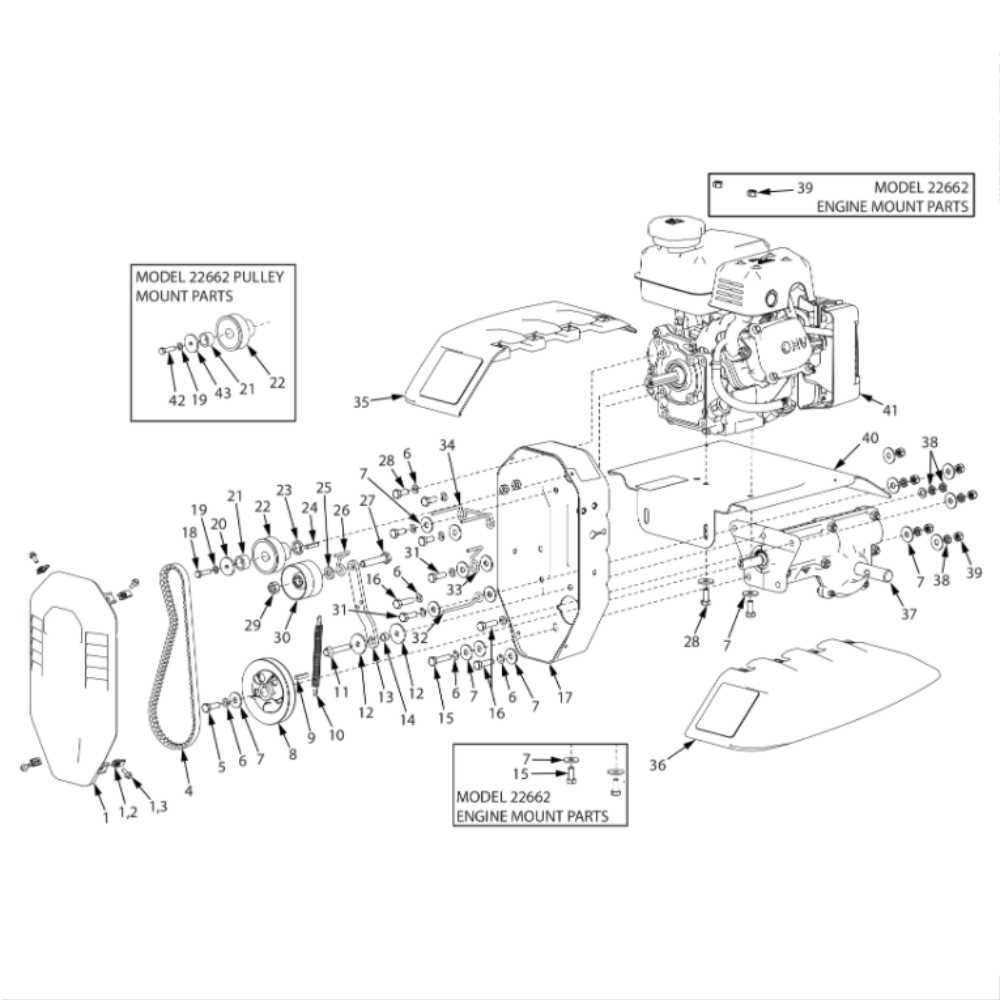
The tine assembly plays a critical role in soil cultivation, ensuring effective loosening and mixing of earth layers. By rotating and penetrating the ground, it aids in breaking up compacted soil, allowing for better aeration and preparation for planting. Understanding the structure and purpose of the tines is key to achieving optimal performance in soil preparation tasks.
Blade Configuration: The tines are equipped with specially shaped blades designed to cut into and churn the soil. These blades work in unison, rotating to create a smooth flow that loosens the earth without damaging its natural structure.
Rotation Mechanism: The tine assembly operates through a rotational motion, with each blade carefully aligned to maximize contact with the soil. The efficiency of this mechanism is crucial for thorough soil breakdown, ensuring the proper depth and consistency in tilling.
The functionality of the tines
Repairing or Replacing Broken Tines
When the digging components of your gardening equipment become damaged or worn out, it’s crucial to address the issue promptly to maintain its effectiveness. Broken or bent blades can lead to inefficient operation, making it difficult to cultivate soil properly. Repairing or replacing these essential tools is a straightforward process that ensures continued performance and helps to avoid further damage to the machine.
The first step in dealing with broken tines is to assess the extent of the damage. If a tine is cracked or severely bent, replacement is often the best option. In some cases, tines may simply require a good cleaning or a slight bend correction. However, for safety and optimal performance, always ensure that the new or repaired tines are securely attached and properly aligned before use.
To replace the damaged tines, start by removing the old ones, which usually involves loosening fasteners or bolts that secure them to the equipment. Once removed, clean the attachment area to ensure a solid fit for the new tines. After securing the new components in place, check the alignment and test the functionality to confirm that everything works smoothly.
Transmission System Breakdown and Operation
The transmission system plays a crucial role in converting the engine’s power into motion. It consists of various components working together to transfer the appropriate amount of force to the wheels or other drive elements. Understanding its operation helps in identifying the most common issues and ensures better maintenance and repair strategies.
Key Components
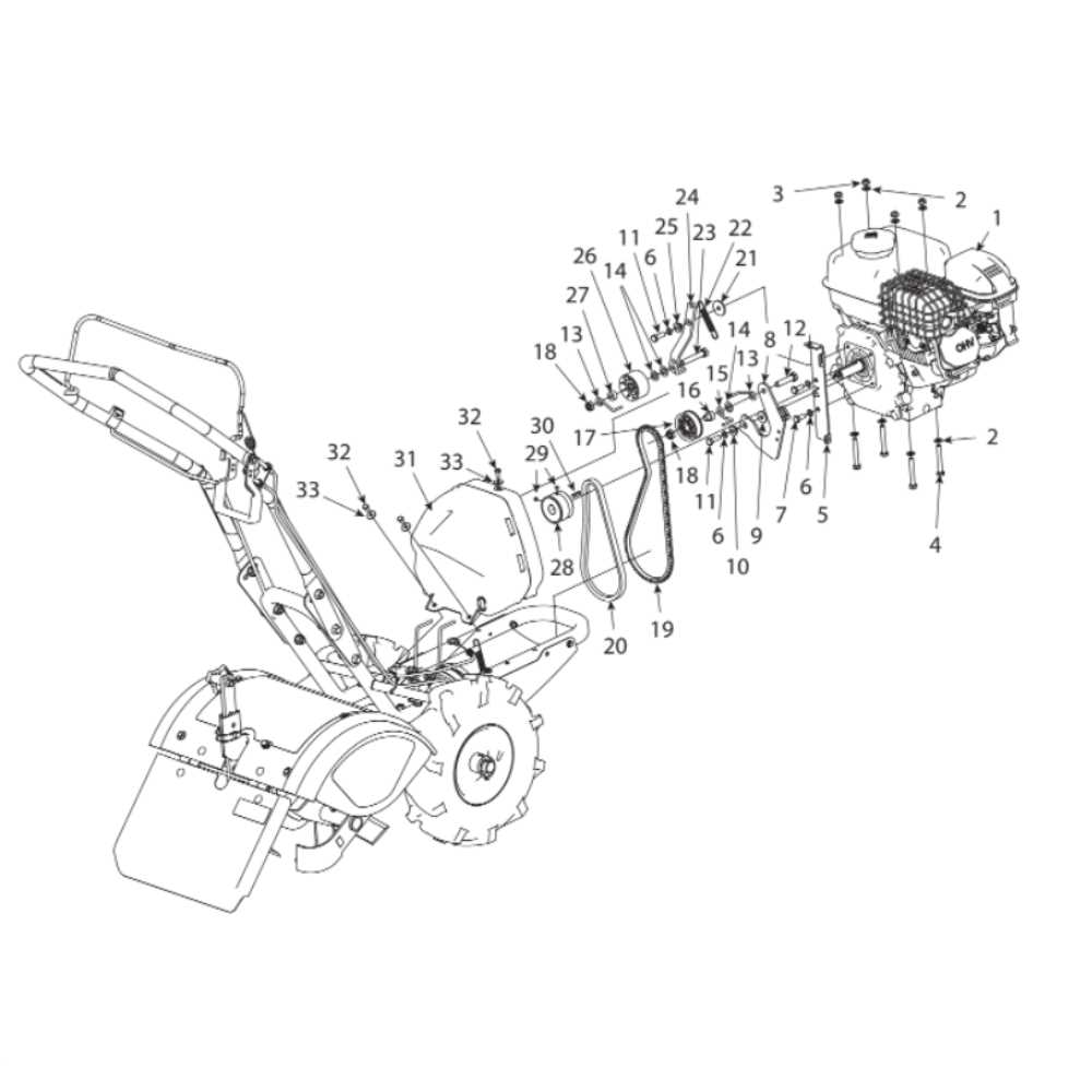
- Gearbox: Responsible for adjusting the torque and speed according to the needs of the system.
- Clutch: Allows smooth engagement and disengagement of gears to prevent damage during operation.
- Drive Shaft: Transfers rotational power from the engine to the wheels or other drive mechanisms.
- Belts and Pulleys: Essential for transmitting motion from one part of the system to another.
How the Transmission System Works
- The engine generates power and sends it to the transmission system.
- The gearbox adjusts the power and directs it to the drive elements.
- The clutch disengages or engages the gearbox, allowing smooth transition between gears.
- The drive shaft or belts transfer the motion to the wheels, propelling the system forward.
Troubleshooting Common Transmission Issues
When dealing with transmission problems, it’s essential to identify the root cause to restore smooth operation. Several factors can contribute to issues in this system, from improper lubrication to worn components. Understanding the symptoms and diagnosing them correctly can save both time and money during repairs.
1. Lack of Response or Slipping
If the transmission seems unresponsive or is slipping, the first step is to check the fluid levels. Low or contaminated fluid is often the culprit. Ensure the correct type of lubricant is used and that there are no leaks in the system. If the fluid level is fine, it could indicate a more serious problem, such as a worn clutch or damaged gears.
2. Unusual Noises or Vibration
Unusual sounds such as grinding or whining may point to issues with the gears or bearings. These noises often indicate internal wear or damage that needs to be addressed promptly. Regular inspection and maintenance can help prevent such issues from escalating.
By taking a systematic approach to troubleshooting and addressing these common issues, you can prolong the lifespan of the system and ensure reliable performance over time.
Drive Belt and Pulley Interaction
The interaction between the drive belt and pulleys is crucial for the efficient transmission of power in any mechanical system. These components work together to transfer rotational energy from one part of the machine to another, ensuring smooth operation. The belt, typically made of durable material, moves over the pulleys, which rotate in response, driving the connected parts. The proper alignment and tension of these components are essential to maintain system performance and prevent unnecessary wear.
Belts are designed to fit snugly around pulleys, and their tension is key to ensuring they grip properly. If the belt is too loose, it can slip, leading to power loss and increased wear. On the other hand, if it’s too tight, it may strain both the belt and pulleys, causing premature damage. Understanding this balance is fundamental to maintaining the system’s efficiency and extending its lifespan.
The pulleys, with their varying sizes and grooves, play a vital role in adjusting the speed and torque transmitted. A smaller pulley, for example, may drive a larger one, altering the speed at which the connected parts move. The smooth interaction between the pulleys and the belt determines how effectively the system transfers energy. Regular inspection and maintenance of these components are necessary to ensure the entire assembly operates seamlessly.
Steps to Properly Adjust the Drive Belt
Ensuring the optimal performance of the drive system relies heavily on correctly setting the tension of the drive belt. A properly adjusted belt helps maintain the efficiency of the mechanism and prevents unnecessary wear. Follow these steps to make the necessary adjustments for smooth operation.
- Turn off the power: Before starting, make sure the equipment is powered off and disconnected from any electrical source to ensure safety.
- Locate the drive belt: Identify the belt and its associated components, ensuring you know how it connects and what needs adjustment.
- Check the tension: Examine the belt’s current tension by pressing down on it with moderate pressure. It should have some give but not be overly loose.
- Adjust the tension: If the belt is too loose, tighten it by adjusting the tensioning mechanism. If it’s too tight, loosen it slightly for better flexibility.
- Test the adjustment: After adjusting the tension, manually rotate the system to check the belt’s movement. It should move smoothly without slipping or excessive resistance.
- Reassemble and test: Once you’re satisfied with the adjustment, reassemble any parts removed during the process. Power on the system and run a brief test to ensure the belt operates properly.
Fuel System Diagram and Components
The fuel system plays a crucial role in supplying the necessary power for engine operation. It includes various components designed to store, filter, and deliver fuel to the engine. Understanding how these parts interact ensures efficient performance and helps in maintaining the equipment in top condition. This section explores the key elements that make up the fuel system and their functions.
Key Components
The fuel system consists of several important components, each with a specific function. The fuel tank is where the fuel is stored, while the fuel filter ensures that impurities do not reach the engine. The fuel lines transport the fuel from the tank to the carburetor or fuel injector, depending on the system type. A fuel pump may also be present to maintain pressure and ensure smooth delivery.
Fuel Delivery Process
Once the fuel enters the system, it passes through the filter to remove any dirt or contaminants. The fuel is then directed towards the engine’s combustion chamber, where it is mixed with air before ignition. Proper fuel delivery is essential for smooth engine operation and optimal power output. Any disruption in this process, such as clogs or leaks, can significantly impact performance.
Maintaining a Clean and Efficient Fuel Flow
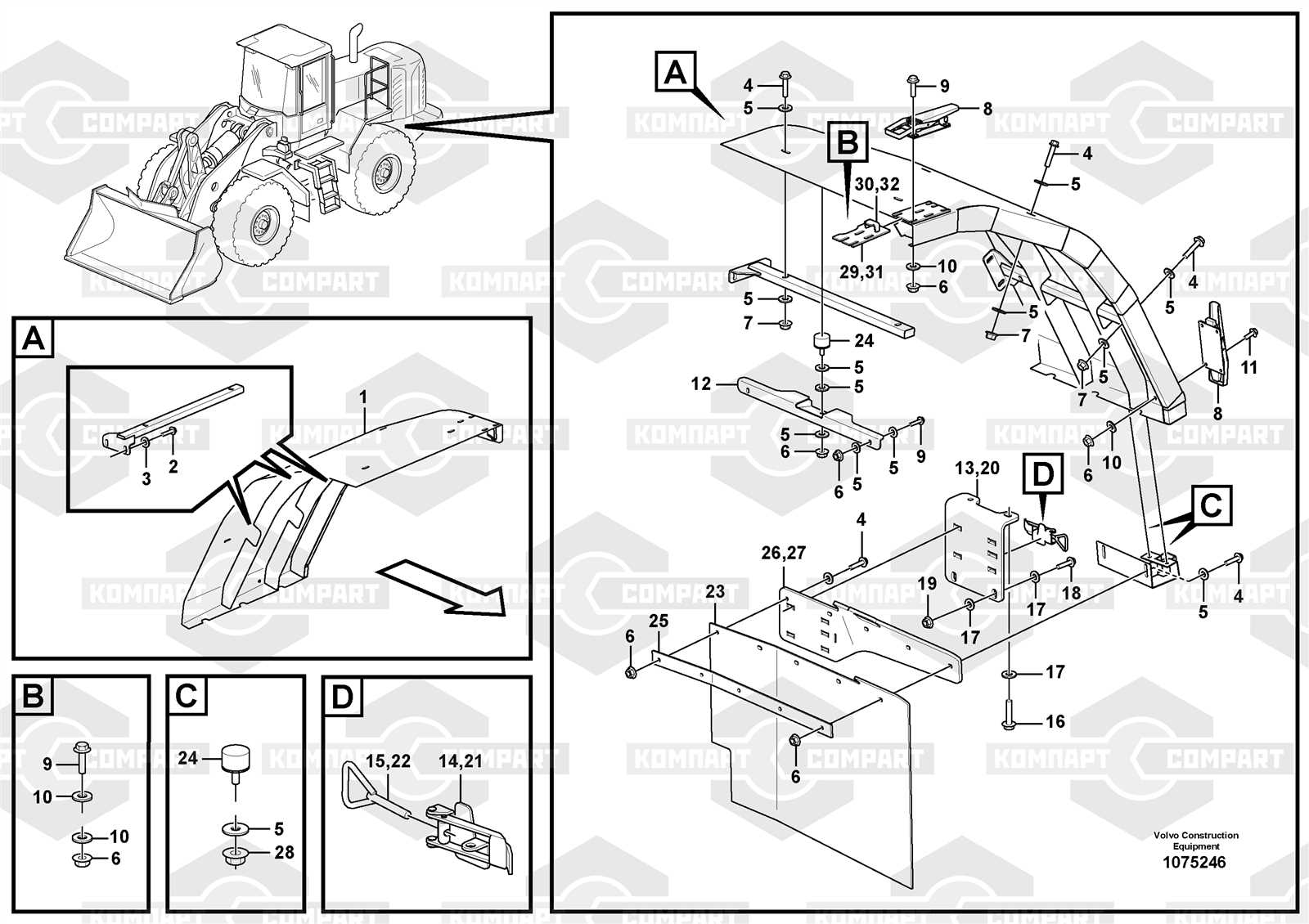
Ensuring that the fuel system remains free of contaminants is essential for optimal engine performance. A well-maintained fuel delivery mechanism ensures smooth operation, reduces wear, and extends the lifespan of the engine. Proper attention to fuel flow can prevent clogs, poor combustion, and other issues that affect performance.
One of the most important aspects is the fuel filter, which traps dirt and debris before they reach the engine. Replacing or cleaning the filter at regular intervals is vital to maintain proper fuel flow. Fuel lines should also be inspected for any leaks or blockages, as these can disrupt the flow of fuel and lead to inefficient operation.
Fuel Flow System Components
Component Function Fuel Filter Prevents debris and contaminants from entering the fuel system Fuel Lines Carry fuel from the tank to the engine; must be checked for blockages or leaks Fuel Pump Ensures consistent fuel delivery to the engine Fuel Tank Holds the fuel; should be kept clean and free from rust or particles By focusing on these components and following a regular maintenance schedule, you can keep the fuel flow efficient and ensure the engine runs smoothly for years to come.
Handlebar Adjustment for Optimal Control
Properly adjusting the handlebars of your equipment is essential for achieving comfortable operation and maximum control. A well-set handlebar ensures that you can manage the device with ease, reducing fatigue and improving overall efficiency during use. Proper positioning allows you to maintain better posture and provides a more stable grip, leading to smoother movements and greater precision in various tasks.
Importance of Correct Handlebar Height
The height of the handlebars significantly affects your ability to maneuver the device. Setting the handlebars at an appropriate height ensures that you maintain a natural arm position, minimizing strain. If the handlebars are too high or too low, it can cause discomfort, reducing your control over the equipment. Always adjust the height to suit your body’s dimensions, ensuring a comfortable reach without overextending or hunching.
Handlebar Angle and Its Impact on Control
Along with height, the angle of the handlebars plays a key role in comfort and control. Adjusting the angle allows you to find the optimal grip and leverage, especially during challenging tasks. A slight tilt forward or backward can make a noticeable difference in your ability to handle the device more efficiently. Experiment with different angles to discover the one that feels most comfortable for your posture and grip strength.
Remember: A few simple adjustments can significantly enhance your experience and performance, ensuring that the task at hand becomes more manageable.