Jiffy Model 30 Parts Breakdown
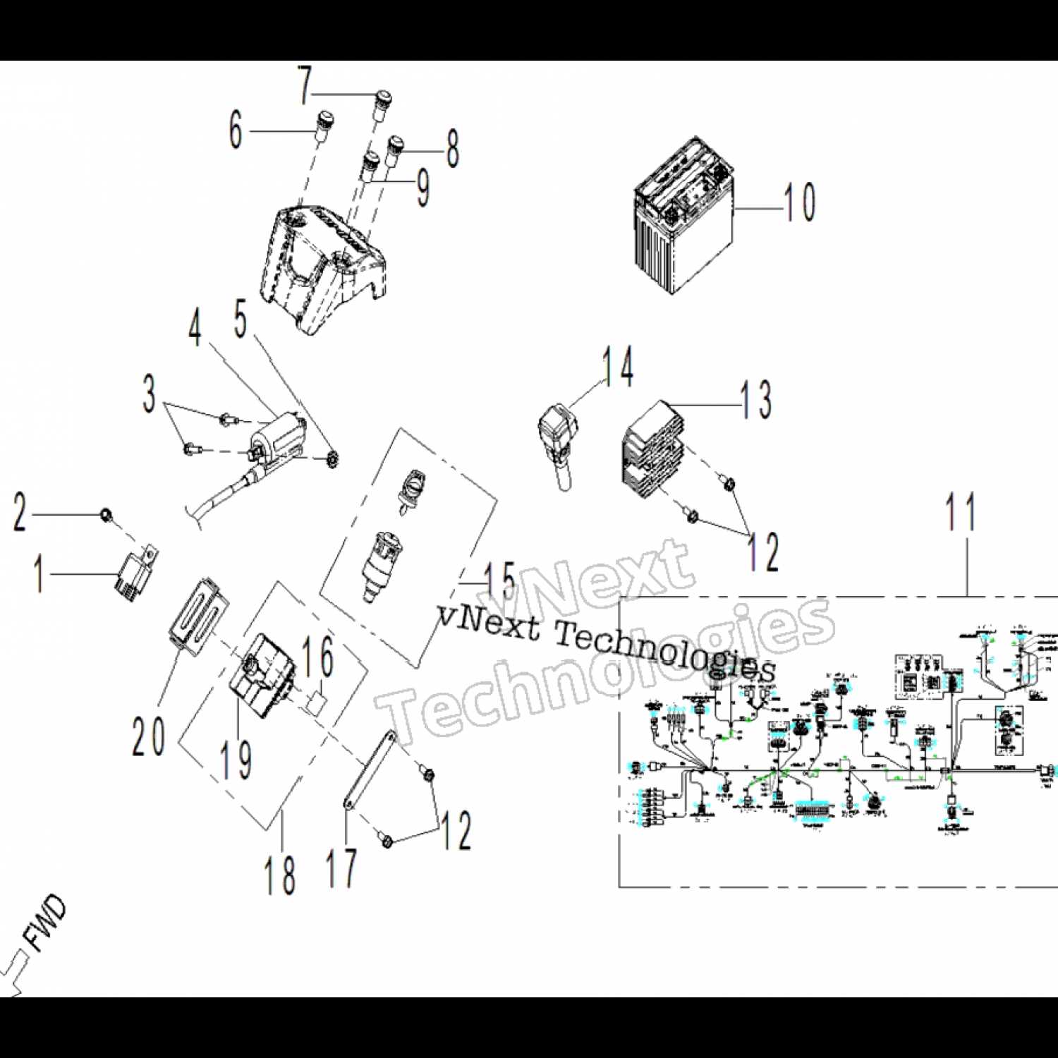
Understanding the structure and functionality of mechanical systems can greatly enhance your ability to maintain and troubleshoot them. Each element plays a crucial role in ensuring smooth operation, and knowing how these elements fit together is key to efficient use and repair.
In the following sections, we’ll explore the arrangement and connection of various crucial components, providing insight into their purpose and interaction. By familiarizing yourself with this layout, you can more easily identify issues and perform necessary maintenance.
Whether you’re working on upkeep or simply seeking to enhance your knowledge, this guide will help you gain a clearer understanding of the system’s inner workings and how each piece functions within the overall mechanism.
Jiffy Model 30 Overview
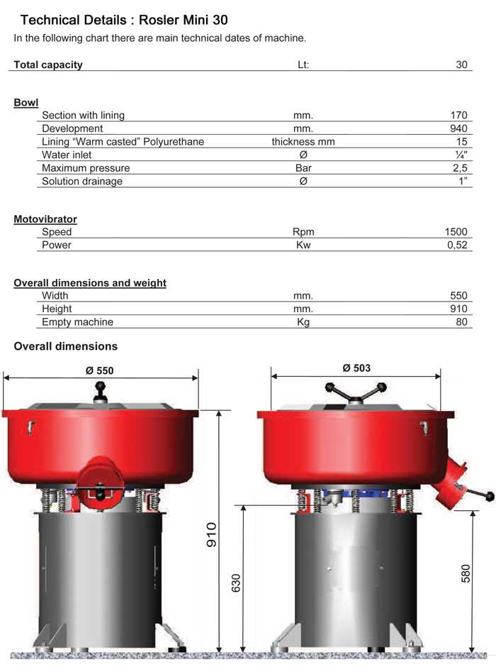
The machine in question is renowned for its reliability and efficiency in outdoor tasks. Designed for those seeking durability and performance, it handles various conditions with ease. This versatile tool has become a popular choice for enthusiasts and professionals alike, thanks to its robust construction and adaptability to different environments.
One of the key highlights of this device is its ease of use, making it accessible even for beginners. It is engineered to provide smooth operation, minimizing effort while delivering consistent results. The ergonomic design ensures comfort during extended use, enhancing the overall experience for the operator.
With an impressive history and proven track record, this equipment continues to meet the demands of users who require dependable performance in challenging situations. It offers the ideal balance between power and portability, making it an essential tool for anyone looking to improve their workflow in the field.
Main Components of the Jiffy Model 30
The system in question consists of several essential elements that work together to ensure efficient operation. Each part is designed to perform a specific function, contributing to the overall performance of the equipment. Understanding these components helps to maintain and optimize the device’s functionality.
Power Assembly
This crucial element is responsible for providing the necessary force to drive the machine. It includes various sub-parts that convert energy into mechanical motion, ensuring smooth and reliable operation.
Drive Mechanism
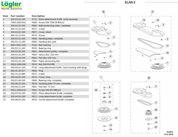
The drive mechanism ensures that all moving components are synchronized, delivering consistent performance. This system includes gears and other parts that transfer power from the source to the working sections of the equipment.
Understanding the Engine Parts Layout
The internal structure of an engine is a complex assembly of components, each playing a crucial role in its function. To maintain the performance of the equipment, it’s important to have a clear understanding of how these elements are organized and work together.
Main Components Overview
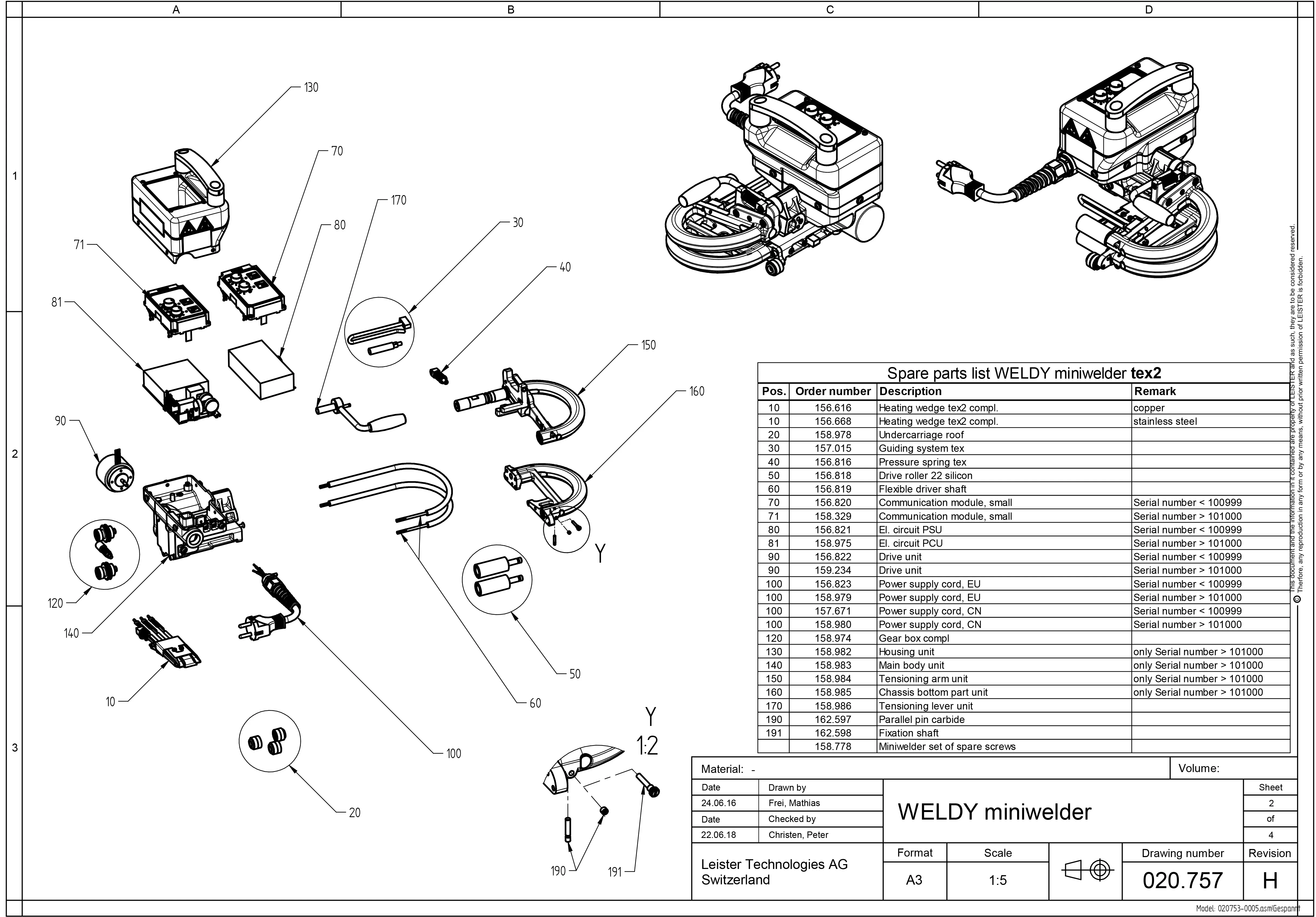
The engine comprises several key elements that ensure it operates smoothly. Below is a simplified breakdown of the essential sections:
- Cylinder: This is where fuel combustion occurs, generating the power necessary for the device to run.
- Piston: Moves within the cylinder, driven by combustion to convert energy into motion.
- Crankshaft: Connected to the piston, it transforms the linear motion into rotational force.
- Spark Plug: Creates the necessary spark to ignite the fuel and air mixture.
Additional Elements and Their Roles
Alongside the core components, other parts support the engine’s overall functionality:
- Air Filter: Prevents debris from entering the engine and causing damage.
- Fuel Line: Ensures a steady supply of fuel from the tank to the engine.
Drill Assembly and Key Features
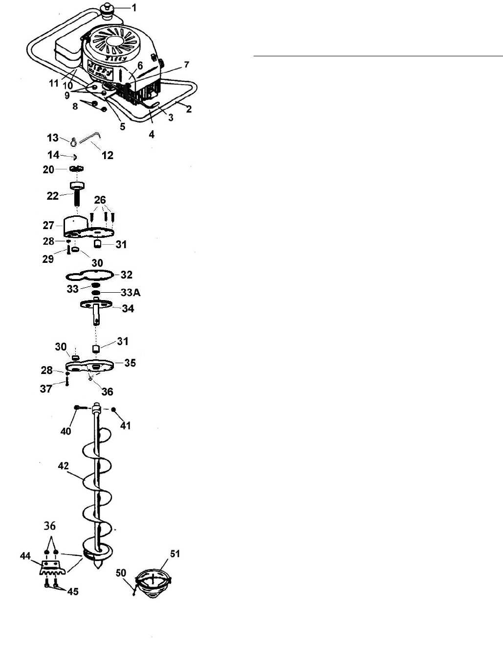
The drill system consists of multiple components working together to ensure optimal performance and efficiency during operation. Understanding the assembly process and recognizing the main attributes of each element will help maintain and enhance the tool’s functionality.
During the assembly, key sections such as the motor housing, transmission, and drive shaft are aligned to form a sturdy and reliable setup. Each piece connects with precision, ensuring smooth rotation and stable drilling action. Special attention is given to securing all elements properly, minimizing wear and maximizing durability over time.
In terms of features, the drill includes advanced mechanisms that offer improved torque control and faster drilling speed. Enhanced safety features, like overload protection, help to prevent damage during intensive use. These characteristics contribute to the overall effectiveness and longevity of the tool in various working conditions.
Throttle Mechanism Breakdown
The throttle system plays a critical role in regulating the power and speed of the machine, ensuring precise control during operation. Understanding the individual components involved in this mechanism can help identify potential issues and maintain optimal performance.
Main Components
The throttle assembly consists of several interconnected parts that work together to manage engine output. These elements must function smoothly to allow efficient control of the engine’s speed and power delivery.
Component Function Throttle Cable Links the throttle handle to the engine, transmitting input for acceleration or deceleration. Return Spring Ensures the throttle returns to its resting position when not engaged. Handle Lever Provides the user interface for controlling the throttle, allowing for adjustments in speed. Common Issues
Fuel System Diagram and Functionality
The fuel delivery mechanism plays a crucial role in the overall performance of the equipment. Understanding its structure and operations is essential for effective maintenance and troubleshooting. This section will explore the key components and their interrelations, highlighting how they work together to ensure optimal fuel supply and engine efficiency.
Key Components of the Fuel Delivery Mechanism
- Fuel Tank: Stores the fuel before it is distributed to the engine.
- Fuel Pump: Responsible for transporting fuel from the tank to the engine.
- Fuel Filter: Removes impurities from the fuel, ensuring clean delivery to the engine.
- Fuel Lines: Pathways through which the fuel travels to reach the engine.
- Carburetor: Mixes air and fuel in the correct proportions for combustion.
Functionality Overview
The operation begins with the fuel being drawn from the tank by the pump. Once pressurized, the fuel travels through the filter, which cleans it before it reaches the carburetor. Here, the fuel is mixed with air to create a combustible mixture, which is then delivered to the engine’s combustion chamber. This process is critical for ensuring the engine runs smoothly and efficiently.
Clutch Assembly and its Importance
The clutch assembly plays a crucial role in the overall functionality of machinery. It serves as the link between the engine and the transmission, allowing for smooth engagement and disengagement of power. This mechanism ensures that the operator can control the speed and torque effectively, which is essential for the machine’s performance and efficiency.
Components of the Clutch Assembly
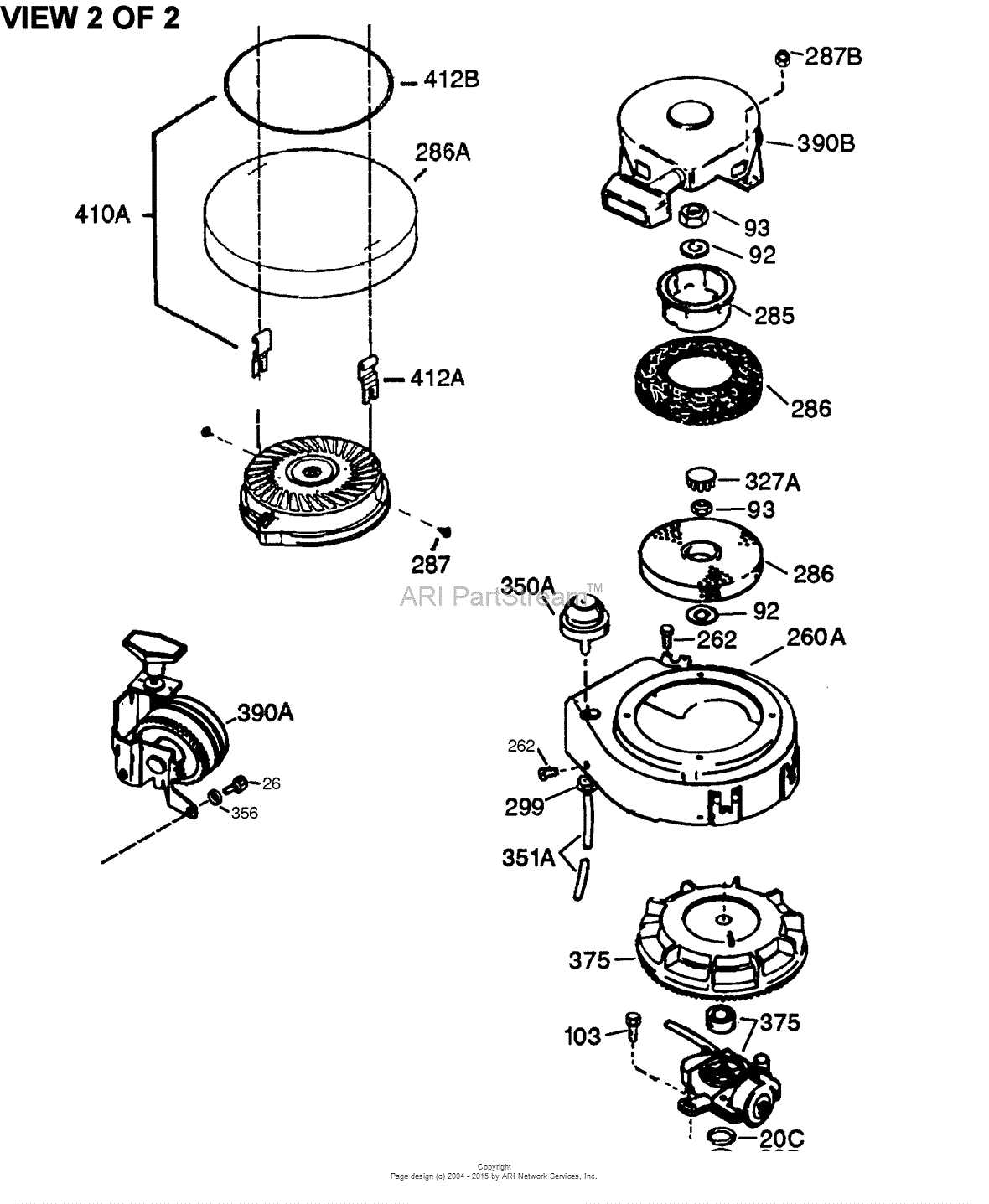
The clutch assembly is comprised of several key elements that work together to facilitate its operation. Each component has a specific function that contributes to the assembly’s overall efficiency. Understanding these parts can help in maintaining and troubleshooting the system effectively.
Component Description Clutch Plate Connects to the flywheel and transfers power from the engine. Pressure Plate Holds the clutch plate against the flywheel, enabling power transfer. Release Bearing Facilitates the disengagement of the clutch by pressing on the pressure plate. Fork Acts as a lever to operate the release bearing during clutch engagement. Significance of Proper Maintenance
Regular inspection and maintenance of the clutch assembly are vital for ensuring optimal performance. Over time, wear and tear can lead to decreased efficiency, resulting in challenges such as slippage or difficulty in engaging gears. Addressing these issues promptly can prevent costly repairs and prolong the lifespan of the equipment.
Blade Configuration and Maintenance Tips
Ensuring optimal performance of your cutting equipment involves understanding the arrangement of the blades and adhering to proper upkeep practices. This section highlights essential guidelines for configuring blades effectively and maintaining them in peak condition for efficient operation.
Blade Arrangement Guidelines
Correctly setting up the blades is crucial for achieving desired cutting results. Consider the following recommendations:
- Assess the specific cutting tasks and choose blade sizes accordingly.
- Ensure blades are aligned parallel to the ground for even cutting.
- Regularly check for wear and replace blades as necessary to maintain performance.
Maintenance Best Practices
Regular maintenance can prolong the lifespan of your cutting tool. Follow these tips:
- Clean the blades after each use to remove debris and prevent rust.
- Sharpen blades periodically to maintain cutting efficiency.
- Store blades in a dry place to avoid moisture exposure.
Handlebar Assembly: Design and Use
The handlebar assembly plays a crucial role in ensuring a smooth and enjoyable experience while navigating various terrains. Its design not only enhances control and maneuverability but also contributes to the overall aesthetic of the vehicle. Understanding the components and their functions can help users maintain and optimize performance.
Key Components
The handlebar assembly consists of several essential elements that work together seamlessly. Each part is engineered to provide stability and responsiveness during use. Below is a brief overview of the primary components:
Component Function Handlebars Provide grip and control for steering Clamp Secures handlebars to the frame Grips Enhance comfort and reduce slippage Controls Allow operation of various functions Importance of Maintenance
Regular inspection and maintenance of the handlebar assembly are vital for ensuring safety and functionality. Proper alignment and secure fittings help prevent accidents and improve performance. Users should periodically check for wear and replace components as necessary to maintain optimal operation.
Air Filter Placement and Maintenance
The effective functioning of any engine heavily relies on proper airflow management. Regular upkeep of the air filtration system is essential for optimal performance and longevity. This section highlights the significance of correct placement and routine maintenance of the air filter to ensure your machinery operates efficiently.
Location of the Air Filter
Understanding where the air filter is situated within the system is crucial for effective maintenance. Typically, it can be found:
- Near the engine compartment, often accessible through the cover.
- Adjacent to the carburetor, allowing for direct airflow.
- In a designated housing that secures it from debris and contaminants.
Maintenance Tips
To maintain the efficiency of the air filtration system, consider the following practices:
- Regularly inspect the air filter for dirt and damage.
- Clean the filter as per the manufacturer’s guidelines or replace it if necessary.
- Ensure the housing is free from obstructions to allow optimal airflow.
- Conduct maintenance checks at scheduled intervals to avoid potential issues.
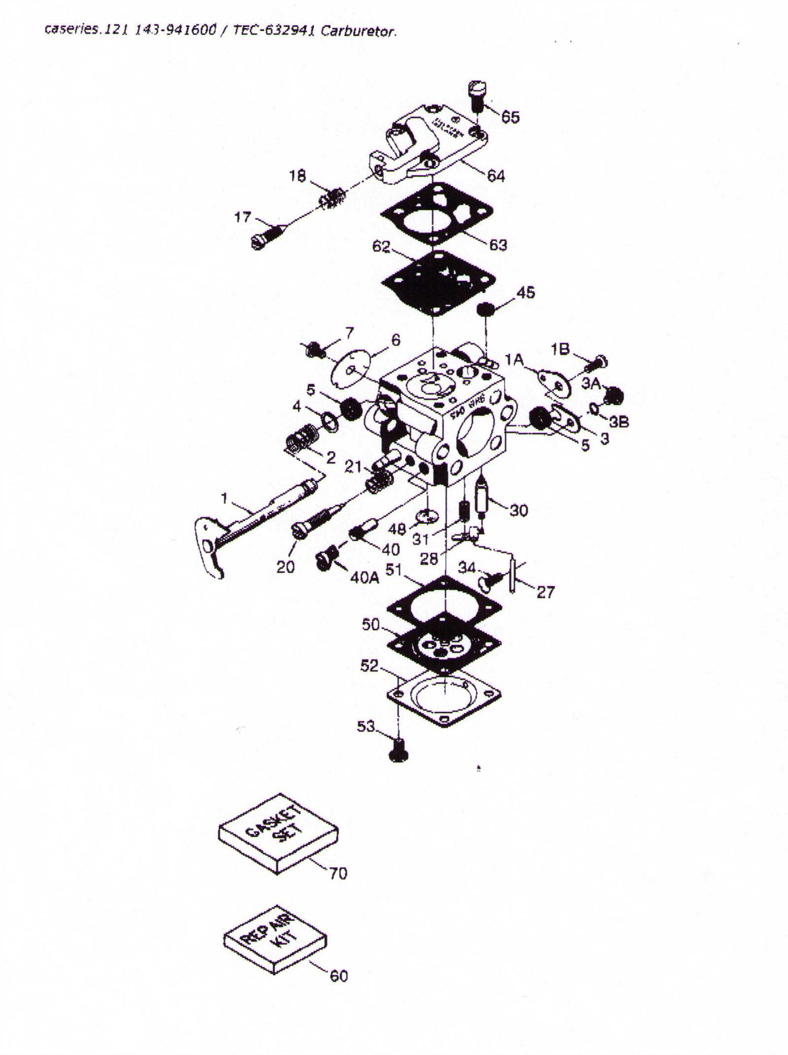
Carburetor Parts and Adjustment Guide
This section focuses on the essential components of the fuel delivery system and provides insights into their fine-tuning. Proper adjustments can significantly enhance performance and efficiency, making it crucial for optimal operation.
Understanding the individual elements that comprise the assembly is key to effective maintenance. Below is a breakdown of the primary components, along with their functions:
Component Description Float Chamber Maintains a consistent fuel level for proper mixing. Jet Regulates the flow of fuel into the airflow, influencing mixture quality. Throttle Valve Controls air intake, affecting engine speed and power output. Needle Valve Adjusts the fuel supply to the mixing area based on engine demand. Choke Restricts airflow during startup for easier ignition in cold conditions. Adjustments should be made carefully, following the manufacturer’s specifications for optimal results. Regular checks can help ensure that each component functions effectively, promoting longevity and reliability.