Understanding the Leeson Motor Parts Diagram for Optimal Performance
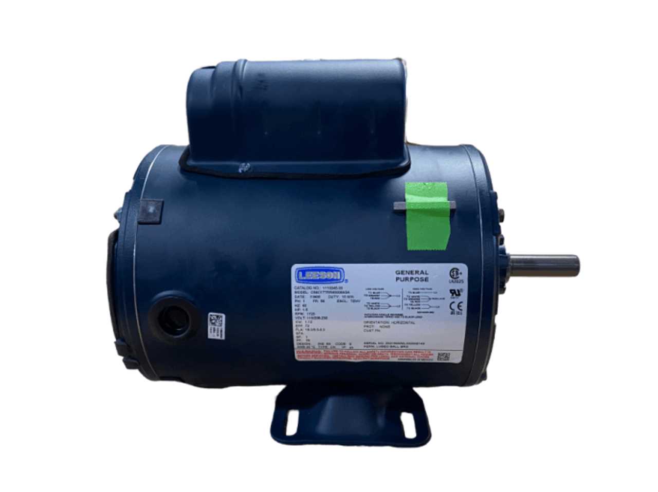
In the realm of electromechanical systems, a clear visual representation of various elements is essential for effective troubleshooting and maintenance. These layouts serve as essential tools for technicians and engineers, enabling them to navigate the complexities of machinery with ease.
By utilizing detailed schematics, users can identify the arrangement and interconnections of individual units, facilitating a deeper understanding of operational functionality. This visual guidance simplifies the process of assembly and disassembly, ensuring that all components are correctly aligned and securely fitted.
Furthermore, having access to comprehensive illustrations can significantly enhance the efficiency of repairs. When components are clearly marked and organized, it reduces the likelihood of errors and accelerates the overall workflow, allowing for timely interventions and improved productivity in various applications.
Understanding Leeson Motor Components
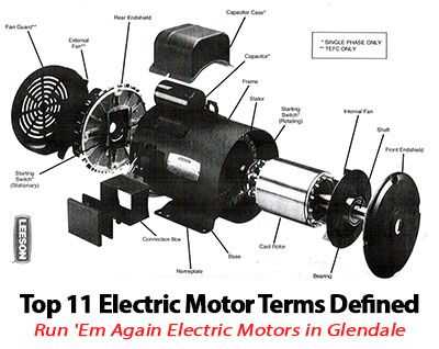
Gaining insight into the various elements that make up a typical rotational device is essential for anyone involved in mechanical systems. Each component plays a critical role in the overall functionality, efficiency, and durability of the apparatus. By familiarizing oneself with these elements, one can better appreciate their interactions and maintenance requirements.
The key components typically found in these machines include:
- Stator: The stationary part that generates a magnetic field.
- Rotor: The rotating element that is influenced by the magnetic field.
- Bearings: Essential for reducing friction and supporting the rotating shaft.
- Shaft: The central part that transmits torque to the load.
- End Bells: Protective covers that encase the internal components.
Understanding the functions of these components enhances troubleshooting capabilities and optimizes performance. For example, recognizing the symptoms of a faulty bearing can lead to timely interventions that prevent more extensive damage.
In addition to the core components, there are also auxiliary features that contribute to the overall efficiency:
- Cooling Systems: Important for managing temperature and prolonging lifespan.
- Control Mechanisms: Allow for precise adjustments in operation based on the application’s needs.
- Mounting Brackets: Provide stability and alignment for the assembly.
By delving into the specifics of each component and their functions, individuals can not only ensure effective operation but also enhance the longevity of the entire system.
Common Issues with Leeson Motors
Understanding frequent complications associated with electric machinery is essential for maintaining efficiency and prolonging lifespan. Various factors can contribute to performance degradation, leading to operational disruptions and costly repairs.
Overheating is a prevalent concern that can stem from insufficient ventilation, excessive load, or electrical malfunctions. This condition often results in reduced efficiency and potential damage to internal components.
Vibration issues may arise from misalignment or imbalance, which not only affects performance but can also lead to accelerated wear and tear. Regular inspections are vital to identify and rectify these discrepancies early.
Electrical failures, such as short circuits or insulation breakdown, can interrupt functionality. These problems typically require prompt attention to prevent further damage and ensure safety.
Noise during operation might indicate underlying mechanical issues. Identifying the source of abnormal sounds can help address problems before they escalate into more serious complications.
By regularly monitoring these common issues, operators can effectively mitigate risks and enhance the reliability of their equipment.
Importance of Accurate Diagrams
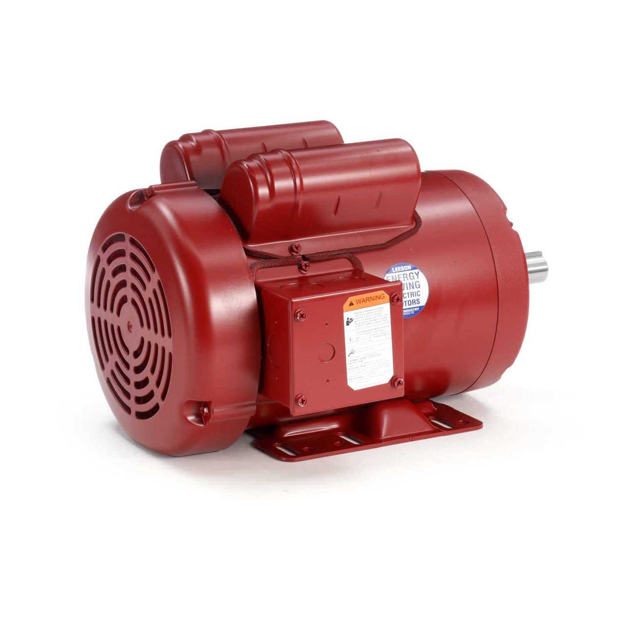
Precision in visual representations is crucial for effective assembly, maintenance, and troubleshooting. Accurate visuals facilitate clear communication among technicians and engineers, enhancing overall efficiency.
- Ensure proper alignment of components.
- Minimize the risk of errors during installation.
- Streamline the diagnostic process.
- Support training and onboarding for new personnel.
Ultimately, well-crafted visuals serve as essential references, enabling users to delve into the specifics of mechanical structures and their functions.
How to Read Motor Schematics
Understanding technical blueprints is essential for effective troubleshooting and repair. Familiarity with symbols and connections allows individuals to interpret complex information, facilitating a clearer comprehension of the equipment’s functioning. This section will provide insights into navigating these essential illustrations.
Key Components and Symbols
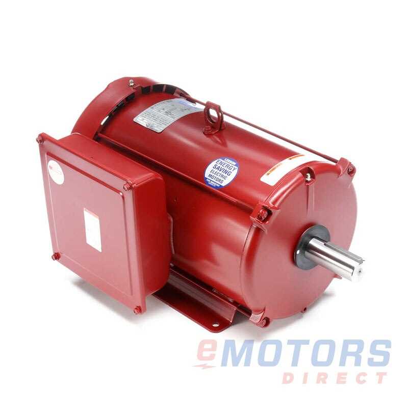
Every schematic consists of various symbols representing components and their interconnections. Familiarizing oneself with these symbols is the first step in understanding the layout and relationships within the system.
| Symbol | Component |
|---|---|
| ◯ | Power Source |
| ⏚ | Ground |
| → | Connection |
| ∎ | Load |
Interpreting Connections
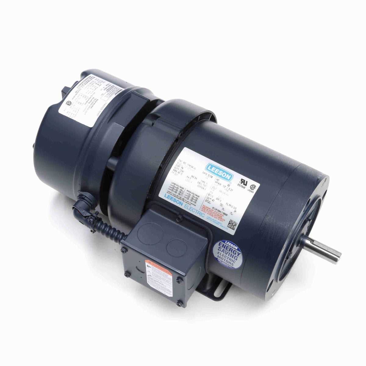
Connections indicate how components are wired together, often represented by lines. Understanding these pathways is crucial for diagnosing issues and ensuring proper functionality. Pay attention to how each element interacts within the larger system to grasp its ultimate operation.
Comparing Leeson to Other Brands
This section explores the differences and similarities between a leading manufacturer and its competitors in the electric machinery sector. By examining various attributes such as performance, reliability, and price, we can gain insights into how these brands stack up against one another.
Performance and Reliability
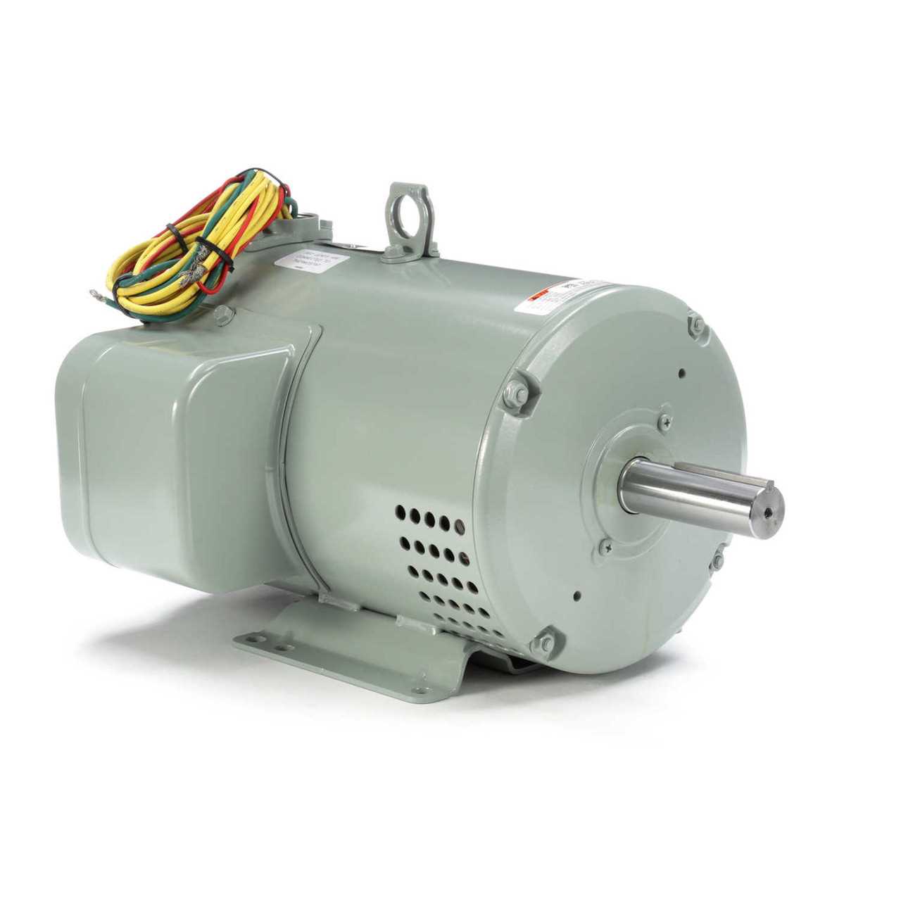
When evaluating efficiency, certain brands may excel in specific applications, offering innovative technologies that enhance output. However, others might prioritize durability, ensuring long-lasting functionality under heavy use, making them suitable for diverse operational environments.
Cost and Value
Pricing strategies vary significantly among manufacturers, with some emphasizing affordability while others focus on premium features that justify a higher investment. Ultimately, understanding the balance between cost and performance is essential for making an informed choice that meets specific needs.
Maintenance Tips for Longevity
Regular upkeep is essential for ensuring the extended lifespan of your machinery. By following a few key practices, you can enhance performance, reduce wear, and avoid costly repairs. This section outlines several effective strategies for maintaining your equipment in optimal condition.
Routine Inspections
Conducting periodic examinations helps identify potential issues before they escalate. Consider the following:
- Check for unusual sounds or vibrations during operation.
- Inspect connections and fasteners for signs of looseness.
- Look for any signs of wear on components.
Regular Cleaning
Keeping your machinery clean is vital for preventing buildup that can hinder performance. Follow these cleaning tips:
- Remove dust and debris from surfaces regularly.
- Use appropriate solvents to clean parts without damaging them.
- Ensure air vents and cooling systems are free of obstructions.
Implementing these practices will contribute to the reliability and efficiency of your equipment, ensuring it operates smoothly for years to come.
Wiring Configurations Explained
Understanding the various arrangements of electrical connections is crucial for ensuring optimal performance in a variety of applications. Each configuration serves a specific purpose, impacting efficiency, output, and overall functionality. Proper comprehension of these setups can greatly enhance the user experience and prevent potential issues during operation.
There are several common configurations that are widely used in industry. Among these, the star and delta arrangements are particularly notable for their distinct advantages. The star configuration offers a higher starting torque, making it ideal for applications requiring an initial boost. In contrast, the delta arrangement excels in providing greater efficiency during continuous operation, making it suitable for long-running tasks.
Additionally, series and parallel configurations are vital to understanding how devices share voltage and current. In a series setup, components are connected end-to-end, resulting in a single path for current flow. This can lead to reduced voltage across each element, while a parallel configuration allows for multiple pathways, enabling a more stable voltage across each part and increasing redundancy.
By grasping these wiring configurations, individuals can make informed decisions when setting up or troubleshooting their equipment, ultimately enhancing both safety and performance.
Identifying Replacement Parts Easily
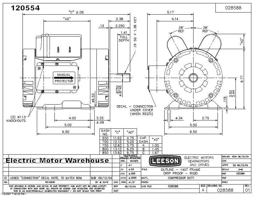
Understanding how to recognize and source components can streamline maintenance and repair processes. This knowledge not only saves time but also ensures the longevity of equipment.
Key Steps to Identify Components
- Consult the original documentation for specifications.
- Examine the existing item for serial numbers or manufacturer codes.
- Utilize online resources or forums for additional guidance.
Resources for Efficient Identification
- Manufacturer websites often provide detailed resources.
- Online marketplaces feature extensive catalogs for comparison.
- Technical support services can offer expert advice.
Role of Diagrams in Repairs
Visual representations play a crucial role in the maintenance and restoration of machinery. These illustrations serve as essential tools that guide technicians through the intricate processes of troubleshooting and fixing various components. By providing a clear overview of how different elements interact, they simplify complex tasks and enhance efficiency.
One of the primary benefits of utilizing these visual aids includes:
- Enhanced Understanding: They offer a straightforward way to comprehend the layout and function of each element, making it easier to identify issues.
- Time-Saving: Quick reference to visual guides minimizes downtime, allowing for more efficient repairs.
- Precision: Accurate illustrations help in assembling and disassembling parts correctly, reducing the likelihood of errors.
- Training Aid: New technicians can learn faster with the help of visual references, gaining practical insights into repair procedures.
In conclusion, these graphical resources are invaluable for anyone involved in the upkeep of machinery. Their ability to convey complex information in an accessible format cannot be overstated, making them indispensable in the repair process.
Resources for Motor Enthusiasts
For those passionate about machinery and its inner workings, a wealth of information and tools is available to enhance knowledge and skills. Engaging with various resources can lead to deeper insights and improved performance in any project.
Online Communities

- Forums dedicated to technical discussions.
- Social media groups for sharing tips and experiences.
- Video tutorials that offer step-by-step guidance.
Books and Publications
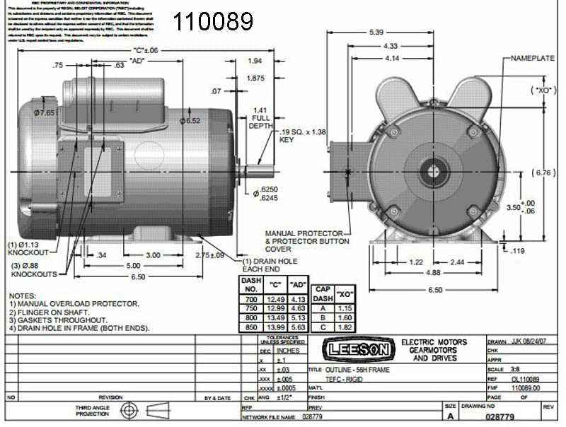
- Comprehensive guides covering fundamentals and advanced techniques.
- Magazines that feature industry news and trends.
- Technical manuals that provide in-depth analyses of components.