Bridgeport Parts Diagram Overview
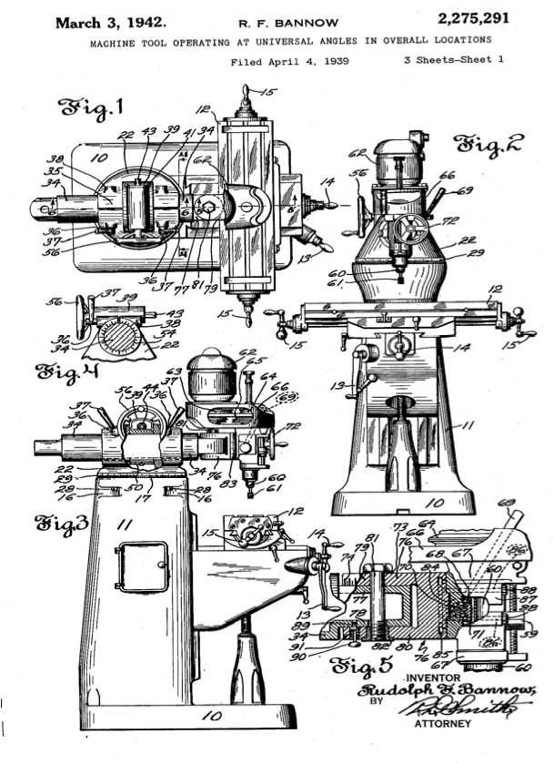
In the following section, we will explore the intricate layout of various elements essential for the functionality of a machining tool. Understanding how these components interact with each other is key to ensuring smooth operations and optimal performance in a workshop environment.
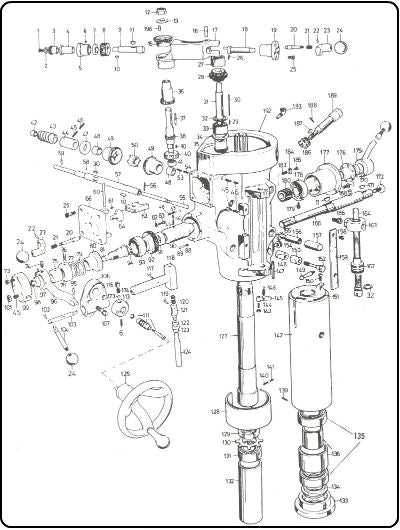
The detailed illustration provides an insight into the structure and positioning of different mechanical parts. By examining each element individually, you can gain a better understanding of their roles within the system, enhancing both maintenance and troubleshooting processes.
Key functional areas include assemblies that govern movement, precision control, and other critical tasks. Identifying the proper placement and connection between these sections is crucial for efficient use and long-term durability.
Milling Machine Components
The construction of a milling machine involves numerous key elements that work together to perform precise cutting operations. These elements are designed to ensure accuracy and efficiency in shaping various materials. Understanding the fundamental components is essential for the effective operation of the machine, as each part plays a critical role in achieving optimal results.
Spindle Assembly: The spindle is a crucial component responsible for holding and rotating the cutting tool. It ensures that the tool remains stable during operation, allowing for smooth and precise cuts.
Work Table: The work table provides a surface on which materials are securely placed during the machining process. Adjustable and sturdy, it allows for positioning the material accurately in relation to the cutting tool.
Motor and Drive Mechanism: The motor powers the machine, while the drive mechanism transmits this power to the spindle, enabling the tool to rotate at various speeds depending on the task.
Control Handles: These handles allow the operator to adjust the machine’s movements and settings manually, providing greater precision and control during operation.
Column and Base: The column supports the major components and provides rigidity, while the base ensures stability and absorbs vibrations, enhancing the o
Understanding the Base of the Machine
The foundation of the milling machine plays a critical role in providing stability and support during its operation. Its robust construction ensures that the entire structure remains steady, minimizing vibrations and ensuring precision. Without a reliable and sturdy base, the accuracy and efficiency of the machine would be significantly compromised.
Structural Integrity
The base is designed with reinforced materials to handle the load of the machine’s upper components. This section typically includes mounting points that anchor the unit to the floor, further enhancing the overall steadiness of the system. These anchoring points are crucial for ensuring that the machine remains secure during high-torque operations, contributing to overall durability.
Supporting Movement
Beyond providing stability, the base also facilitates the smooth movement of various machine components. Integrated channels and pathways guide mechanical elements, ensuring consistent alignment throughout the machining process. By supporting seamless transitions, the base helps maintain optimal performance during prolonged usage.
Knee Mechanism and Its Functionality
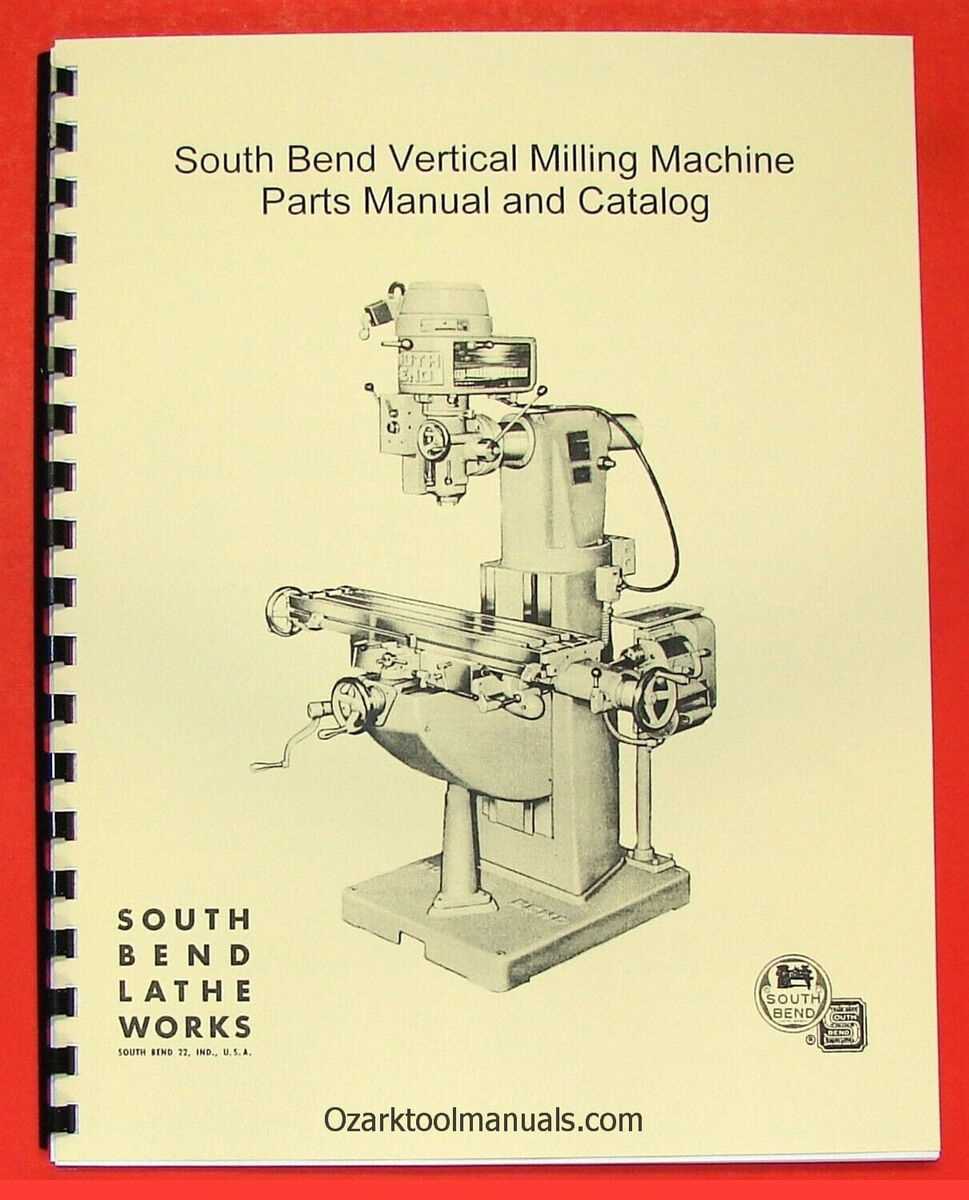
The knee mechanism plays a crucial role in the operation of vertical milling machines, allowing for precise adjustments in the positioning of the table. This feature provides essential support and flexibility during various machining processes, enhancing the overall efficiency and control of the equipment.
| Component | Function |
|---|---|
| Knee Handle | Enables vertical movement, adjusting the height of the table to accommodate different workpiece sizes. |
| Gibs | Help maintain stability and minimize play during the movement of the knee, ensuring smooth operation. |
| Locking Mechanism | Secures the knee in the desired position, preventing unwanted shifts during the machining process. |
The smooth vertical motion provided by the knee system
Exploring the Spindle Assembly
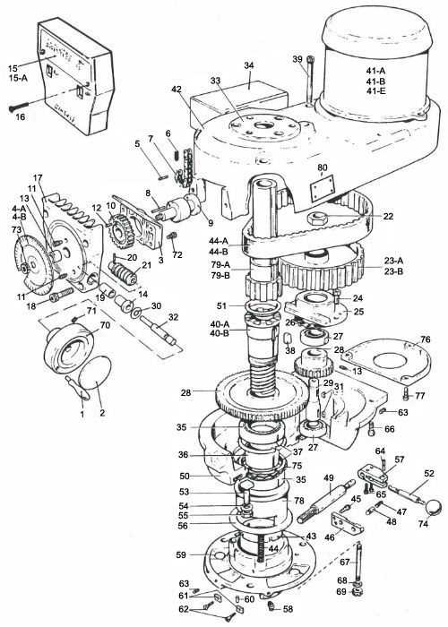
The spindle assembly plays a crucial role in the overall functionality of the machine, ensuring smooth and precise operation. It is responsible for transmitting motion and controlling various processes within the system. Understanding its structure and components is essential for maintaining efficiency and performance.
- Central Shaft: This element is at the core, driving the rotational movement necessary for the tool’s operation.
- Bearings: These support the shaft, minimizing friction and ensuring stable rotation under load.
- Housing: Encases the entire assembly, protecting the internal components from wear and environmental factors.
- Drive Mechanism: Provides the necessary power and torque for the spindle’s motion, connecting to the main motor.
Proper care and maintenance of each part are essential for prolonging the assembly’s life and maintaining optimal performance.
Quill Mechanism: Essential Operations
The quill mechanism is a key component in various machines, responsible for enabling precise vertical movement during operations. Its function allows for accurate control, providing the operator with the ability to adjust positioning with high precision. Understanding its basic movements is crucial for ensuring efficiency and maintaining smooth operation during tasks.
Vertical Adjustment and Control
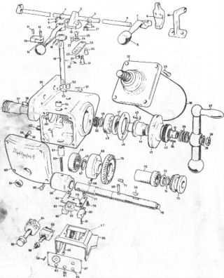
One of the most critical aspects of the quill mechanism is its ability to move vertically in a controlled manner. This allows for fine adjustments to be made, ensuring the desired depth is achieved. A system of calibrated knobs and levers usually controls this movement, offering the operator the precision required for detailed work.
Maintenance and Proper Use
To keep the quill functioning optimally, regular maintenance is necessary. Lubrication of moving parts, checking for wear, and ensuring smooth operation are essential tasks. Proper care helps in avoiding unexpected issues during use, ensuring that the mechanism operates as intended over time.
Table Movement and Adjustment System
The mechanism responsible for the lateral and vertical positioning of the work surface is crucial for ensuring precision and efficiency in machining operations. This system enables operators to make fine adjustments, facilitating the accurate placement of materials during various tasks.
Key components of this assembly typically include a series of lead screws and handwheels that allow for smooth and controlled motion. The integration of bearings plays a significant role in minimizing friction, enhancing the overall functionality of the system.
Furthermore, the design often incorporates locking mechanisms to secure the table in place once the desired position is achieved. This ensures stability during operations, allowing for consistent results and improved safety standards.
Proper maintenance of this system is essential. Regular lubrication and inspection of the moving parts can prevent wear and tear, prolonging the lifespan of the equipment while maintaining optimal performance.
Importance of the Motor in Performance
The efficiency of a mechanical system significantly hinges on the functionality of its motor. This vital component plays a crucial role in determining how effectively the machinery operates, influencing both speed and output quality. Understanding the motor’s impact is essential for optimizing overall performance and ensuring reliability in various applications.
Role in Efficiency
The motor is responsible for converting electrical energy into mechanical power. Its design and specifications directly affect how efficiently this conversion occurs. An optimized motor minimizes energy wastage, leading to lower operational costs and enhanced productivity. In contrast, a poorly designed or malfunctioning motor can result in significant energy losses, affecting the entire system’s performance.
Influence on Output Quality
Another critical aspect of the motor’s significance lies in its influence on the quality of the output produced. A high-performance motor ensures precise control over the speed and torque, which are essential for achieving desired results. Variations in motor performance can lead to inconsistencies in product quality, making it vital to select the right motor for specific applications.
| Motor Type | Efficiency Rating | Typical Applications |
|---|---|---|
| AC Motor | High | Industrial equipment, fans |
| DC Motor | Moderate | Robotics, small appliances |
| Stepper Motor | High | CNC machines, 3D printers |
Drive Belt and Pulley Mechanism
The drive belt and pulley system is a crucial element in various machines, facilitating the transfer of rotational motion from one component to another. This mechanism relies on the interaction between flexible belts and grooved wheels to ensure efficient power transmission, enabling machinery to operate smoothly and effectively.
In this configuration, the belt encircles the pulleys, creating a direct link that allows for the conversion of motor power into usable energy for other parts of the system. The choice of materials and the design of the belt and pulleys significantly influence the overall performance, durability, and efficiency of the mechanism.
| Component | Description |
|---|---|
| Belt | A flexible loop that transmits power between pulleys, usually made of rubber or synthetic materials for flexibility and durability. |
| Pulley | A wheel with a groove around its edge that guides and supports the belt, crucial for direction and tension adjustment. |
| Tensioner | A device that maintains the appropriate tension in the belt, preventing slippage and ensuring efficient power transfer. |
| Idler | A supplementary pulley used to guide the belt and help maintain its tension, aiding in the smooth operation of the mechanism. |
Exploring the Head Assembly Structure
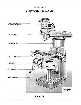
The head assembly is a critical component that plays a vital role in the overall functionality of the machine. Understanding its structure and various elements is essential for effective operation and maintenance. This section delves into the intricacies of this assembly, highlighting its significance and the interrelation of its parts.
Key Components of the Head Assembly
The head assembly comprises several integral parts, each contributing to the overall performance. It typically includes the spindle, which facilitates rotation, and the housing, which provides stability. Additionally, various gears and levers work in harmony to enable precise adjustments and control over the machining process.
Importance of Proper Maintenance
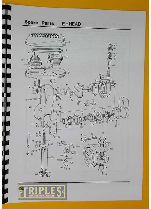
Regular upkeep of the head assembly is paramount to ensure optimal performance and longevity. Neglecting this area can lead to operational inefficiencies and potential failures. By routinely inspecting and servicing the assembly, users can maintain high levels of accuracy and reliability in their work.
Lubrication Points and Maintenance Tips
Proper lubrication is essential for ensuring the longevity and smooth operation of machinery. Regularly maintaining key areas not only prevents wear and tear but also enhances overall performance. Understanding where to apply lubricants and how to perform routine checks can significantly extend the lifespan of your equipment.
Key Areas for Lubrication
Focus on high-friction components, such as bearings, gears, and slideways. These areas are prone to significant wear if not properly lubricated. Using the correct type of lubricant is crucial; consult the manufacturer’s guidelines to select the appropriate oil or grease for each component. Regularly inspect these points to ensure they are not dry or damaged, as this can lead to costly repairs.
Maintenance Practices
Establish a consistent maintenance schedule that includes checking lubrication levels and applying fresh lubricant as needed. Additionally, keep the surrounding area clean to prevent contaminants from entering the system. Implementing a preventive maintenance routine will help identify issues early on, reducing the risk of unexpected breakdowns and ensuring optimal operation.
Power Feed System Overview
The power feed mechanism is an essential component that enhances the functionality of milling machines. This system automates the movement of the workpiece or tool, allowing for precise and efficient operations. By facilitating controlled feed rates, it significantly reduces the manual effort required, leading to improved accuracy and productivity.
Typically, the power feed system comprises various elements that work together to ensure smooth operation. These components include motors, gears, and drive assemblies, all designed to provide reliable performance. The integration of such a system allows for seamless transitions between different machining tasks, making it a vital addition for users seeking to optimize their workflow.
Overall, the implementation of a power feed system not only streamlines processes but also enhances the capabilities of machining equipment. By utilizing this technology, operators can achieve higher levels of precision and repeatability, ultimately leading to superior results in their projects.
Common Issues with Bridgeport Parts
When working with machinery components, several challenges may arise that can affect performance and efficiency. Understanding these common problems can aid in preventive measures and ensure smoother operations.
Frequent Challenges
- Wear and Tear: Over time, components may experience deterioration, leading to decreased effectiveness.
- Alignment Issues: Improper alignment can result in operational difficulties and can cause additional strain on other components.
- Lubrication Failures: Insufficient lubrication may lead to increased friction, which can accelerate wear and potentially cause failures.
- Corrosion: Exposure to harsh environments can result in rust and other forms of corrosion, compromising structural integrity.
Signs of Trouble
- Unusual Noises: Strange sounds during operation may indicate internal problems.
- Inconsistent Performance: Variability in output can signal underlying issues that need to be addressed.
- Overheating: Excessive heat can indicate insufficient lubrication or other mechanical failures.
- Vibration: Uncharacteristic vibrations may suggest misalignment or damage to components.