Hobart D300 Parts Diagram for Easy Maintenance and Repairs
In any industrial kitchen, the mechanical devices used for blending and kneading play a critical role in daily operations. Over time, these machines may require attention or replacement of certain elements to ensure peak performance. Knowing the inner workings and the individual elements of such equipment can greatly help in identifying what needs maintenance or replacement.
Each element within these machines serves a specific function, contributing to their overall efficiency and durability. From the motor assembly to smaller gears and seals, understanding these components is key to keeping the equipment in optimal condition. Proper maintenance, along with a clear overview of the internal and external elements, will ensure longevity and reduce the likelihood of downtime.
This guide provides a detailed breakdown of the essential elements, helping users identify, maintain, and replace them as needed. Whether you’re dealing with large components or intricate details, having a clear understanding of the machine’s structure will assist in efficient troubleshooting and repair.
Understanding the Hobart D300 Mixer Parts
In this section, we will explore the essential components that make up this kitchen appliance. Each element plays a critical role in ensuring smooth operation and longevity, contributing to the machine’s efficiency and durability.
Let’s break down the primary elements involved:
- Motor Assembly – This is the powerhouse, responsible for driving the mixing process. Proper maintenance is crucial for consistent performance.
- Transmission System – The transmission converts energy from the motor into mixing power. This mechanism controls speed and torque during operation.
- Agitator Attachments – These interchangeable tools handle a variety of tasks, from kneading dough to whipping cream, depending on the attachment used.
- Bowl Lift Mechanism – Designed for adjusting the height of the mixing bowl, this component allows for easy placement and removal of ingredients.
- Control Panel – A set of controls for adjusting speed, power, and other settings, offering precision and ease of use during operation.
Main Components of the Hobart D300
Understanding the essential elements of this industrial mixer is key to ensuring its effective operation and long-term reliability. Each section of the machine plays a specific role, contributing to the overall functionality and performance required in heavy-duty kitchen environments.
Motor Assembly
The motor is the driving force behind the machine, delivering the power needed for various mixing speeds. Its robust construction allows for continuous operation, handling both light and dense mixtures with ease.
Control Panel
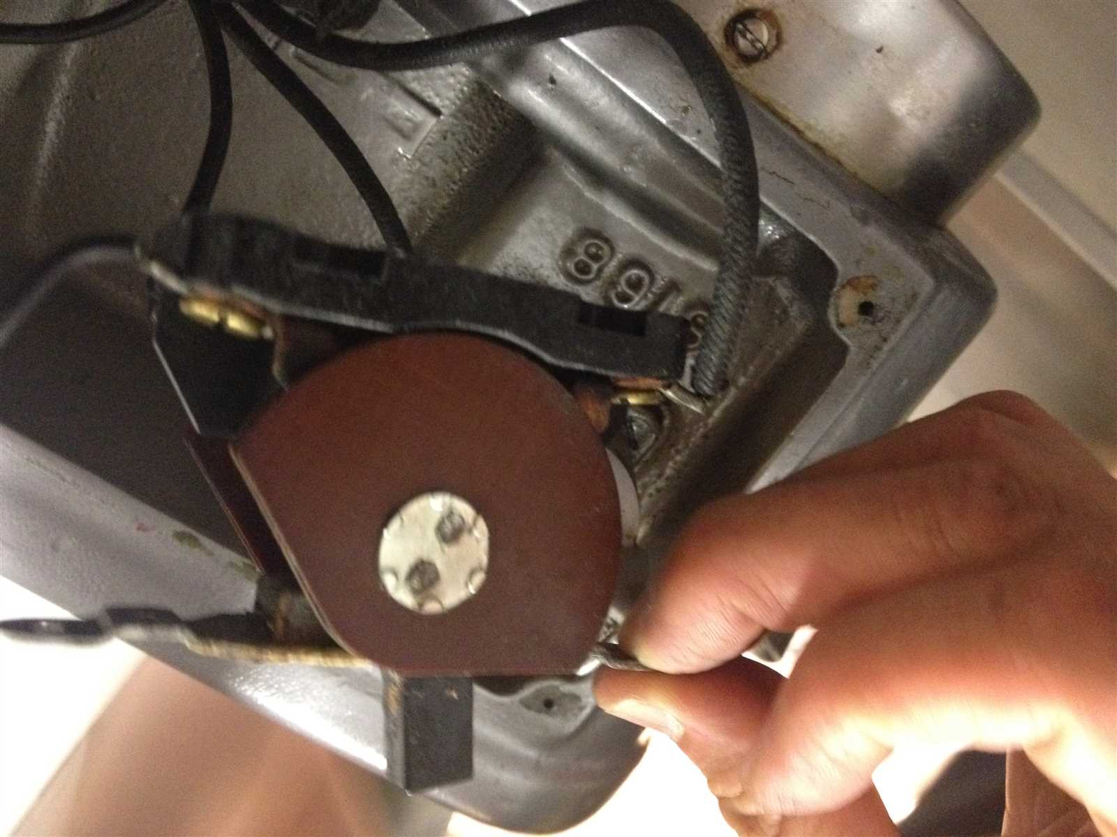
The control panel is the interface used to adjust speed and other settings. Designed for ease of use, it ensures precise control over the mixing process, enabling users to achieve consistent results. Strong safety features are built into the system to prevent operational errors.
Internal Gear Mechanism Overview
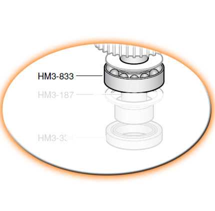
The internal gear system is a critical component that ensures smooth and efficient operation in mechanical devices. Its primary function is to transfer rotational force between interconnected elements, allowing the entire system to operate with precision and consistency.
Key Features of the internal gear design include enhanced durability and the ability to handle high loads, which make it ideal for industrial applications. The unique structure of internal gears allows for compact designs, making them well-suited for equipment where space is limited.
The interaction between the gears, which often involves a central gear engaging with surrounding internal teeth, minimizes friction and wear, ensuring long-lasting performance. This mechanism also enables smoother transitions between different speeds and torque levels, contributing to the overall reliability of the system.
Motor and Electrical System Breakdown
The motor and electrical system of this industrial equipment play a crucial role in ensuring efficient operation. Understanding the internal components and connections allows for better maintenance, troubleshooting, and upgrades when needed. In this section, we will explore the key elements of the system, highlighting their functions and interconnections.
The motor is responsible for converting electrical energy into mechanical motion, driving the machine’s core functionality. It is powered by a set of electrical connections that include wires, terminals, and control units, all working in sync to provide stable and reliable performance. Proper care of the electrical system ensures smooth operation, preventing downtime and ensuring longevity.
Critical components of the system include the main power supply, fuses, and relays, which regulate and protect the motor from overloads and short circuits. These elements form a safety network that helps to prevent damage to the machine’s electrical infrastructure. Regular inspections of these parts help identify potential issues early, reducing the risk of unexpected failures.
Exploring the Bowl and Attachments
The bowl and attachments are key components that define the versatility of any kitchen mixer. They work together to allow various mixing, whipping, and kneading tasks to be performed efficiently, enhancing the machine’s functionality.
The bowl is designed to handle different volumes of ingredients, making it suitable for both small and large batches. It is securely held in place during operation, ensuring stability even when handling heavy doughs or mixtures.
Attachments such as beaters, whisks, and dough hooks are easily interchangeable, offering flexibility for a range of food preparation tasks. These tools are tailored for specific needs, allowing users to customize the machine’s functionality based on the task at hand.
Maintenance Guide for Key Parts
Regular upkeep of essential components is vital for ensuring optimal performance and longevity of equipment. By following a systematic maintenance approach, operators can prevent potential issues and enhance the overall efficiency of their machinery.
Regular Inspection
Conducting routine checks helps identify wear and tear before they escalate into significant problems. Focus on the following areas:
- Electrical Connections: Ensure all wiring is intact and free from corrosion.
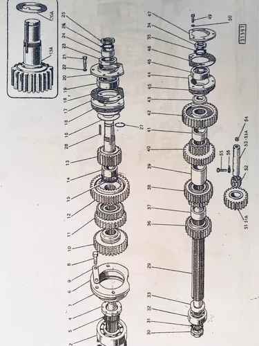
- Moving Parts: Examine gears and bearings for signs of wear.
- Seals and Gaskets: Check for leaks or deterioration that could affect performance.
Cleaning Procedures
Keeping components clean is essential for preventing buildup that can impair function. Implement the following cleaning practices:
- Use appropriate solvents to remove grease and grime from surfaces.
- Ensure filters are cleaned or replaced as necessary to maintain airflow.
- Regularly check and clear any blockages in ventilation systems.
Common Issues with the Hobart D300
The industrial mixer is a valuable asset in any kitchen, but like any mechanical equipment, it can encounter various challenges over time. Understanding these potential problems can help users maintain optimal performance and extend the lifespan of the device.
One frequent issue is motor overheating, which can lead to reduced efficiency and eventual failure. This often occurs due to prolonged use without adequate breaks or insufficient cooling. Ensuring proper ventilation and allowing the mixer to rest can mitigate this problem.
Another common concern is unusual noises during operation. This can indicate a variety of underlying problems, such as worn bearings or misaligned components. Regular inspection and timely maintenance can help identify these issues before they escalate.
Additionally, inconsistent mixing can affect the quality of food preparations. This issue may arise from improper attachment settings or worn-out mixing tools. Users should regularly check and replace any components that show signs of wear to ensure effective mixing performance.
Finally, power interruptions can also pose a challenge, disrupting workflows and potentially damaging the mixer. It’s essential to ensure that the electrical supply is stable and to use surge protectors where necessary to prevent such issues.
Replacement Options for Worn Components
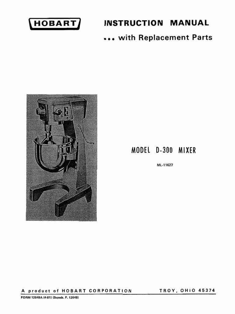
When the machinery begins to show signs of wear, identifying suitable alternatives for its components is crucial to maintaining optimal functionality. Over time, certain elements may degrade or fail, impacting the overall performance. Having a clear understanding of available options can ensure efficient repairs and prolong the life of the equipment.
Aftermarket Solutions
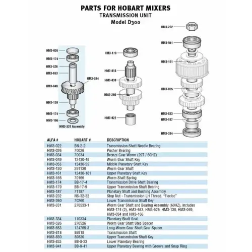
Aftermarket replacements are often a cost-effective choice, providing comparable quality at a lower price. Many manufacturers offer compatible components designed to fit seamlessly into the original machinery. It is essential to research the reliability of these alternatives, as they can vary significantly in durability and performance.
OEM Components
For those seeking guaranteed compatibility and performance, original equipment manufacturer (OEM) components are the safest bet. These parts are made to the same specifications as the original ones, ensuring proper function and longevity. Although they might come at a premium, the peace of mind and assurance of quality can justify the investment.
In conclusion, whether opting for aftermarket solutions or sticking with OEM components, understanding the options available for worn machinery parts can lead to effective maintenance and enhanced equipment lifespan.
Identifying the Agitator and Shaft
Understanding the components of a mixing machine is essential for proper maintenance and efficient operation. Among these components, the mixing tool and its corresponding rod play a crucial role in the blending process. Recognizing these parts and their functions is vital for ensuring optimal performance and addressing any potential issues that may arise.
Agitator Overview
The mixing tool, often referred to as the agitator, is designed to thoroughly combine ingredients within a bowl or container. This component typically features a unique shape that enhances its ability to reach all areas of the mixing vessel, ensuring even distribution of materials. It is important to regularly inspect the agitator for any signs of wear or damage, as this can affect the overall efficiency of the mixing process.
Shaft Functionality
The rod, or shaft, serves as the connection between the motor and the mixing tool. It transmits power from the motor, allowing the agitator to rotate and perform its blending function. Proper alignment and secure attachment of the shaft are crucial for smooth operation. Any misalignment can lead to excessive wear or potential failure of the mixing system, highlighting the importance of regular checks and maintenance.
Drive System and Belt Arrangement
The drive mechanism and belt configuration are crucial for the efficient operation of industrial mixers. This system ensures that the mixing components function smoothly, providing the necessary torque and speed to achieve optimal mixing results. Understanding the arrangement of belts and the drive elements is essential for proper maintenance and troubleshooting.
Components of the Drive System
The drive system comprises several key elements that work in unison. These components include the motor, pulleys, and belts, which collectively facilitate the transfer of power from the motor to the mixing mechanism.
Belt Configuration
The arrangement of the belts plays a significant role in determining the performance of the mixing equipment. A proper alignment ensures that the belts operate efficiently without slipping or excessive wear. Below is a table illustrating the typical components involved in the drive system and their respective functions:
| Component | Function |
|---|---|
| Motor | Provides the power necessary for operation. |
| Pulley | Transmits motion from the motor to the belt. |
| Belt | Transfers power from the pulley to the mixing assembly. |
| Tensioner | Maintains proper tension in the belt to prevent slippage. |
Lubrication Points and Guidelines
Proper maintenance of equipment significantly enhances its lifespan and ensures optimal performance. Regular lubrication is crucial for reducing friction and wear between moving components, thereby preventing costly repairs. This section outlines essential lubrication points and provides practical guidelines for effective maintenance.
Key Lubrication Areas
It is vital to identify the primary areas that require regular lubrication. Common points include gearboxes, bearings, and any joints or pivot points that experience continuous movement. Ensuring these areas are adequately serviced will help maintain smooth operation.
Recommended Lubricants
When selecting lubricants, consider the manufacturer’s specifications regarding viscosity and type. High-quality grease or oil will provide superior protection against wear and corrosion. Always opt for products specifically designed for industrial applications to achieve the best results.
Lubrication Frequency
Establishing a lubrication schedule is essential. Regular inspections should determine the frequency of application, typically every few weeks or based on operational hours. Keeping a detailed log of lubrication activities can aid in tracking maintenance and ensuring no points are overlooked.
Application Techniques
Employ appropriate methods for applying lubricants. For example, a grease gun can be useful for filling grease fittings, while oilers may be better suited for applying liquid lubricants to specific components. Avoid over-lubrication, as this can attract dirt and debris, leading to potential damage.
By following these guidelines, equipment operators can significantly improve operational efficiency and extend the service life of their machinery.
Troubleshooting Electrical and Mechanical Failures
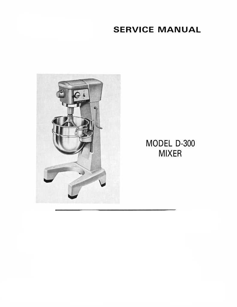
Identifying and resolving electrical and mechanical issues in industrial equipment is crucial for maintaining operational efficiency. A systematic approach to diagnosing problems can significantly reduce downtime and enhance performance. This section provides guidance on common troubleshooting techniques that can help in identifying the root causes of malfunctions.
Electrical Troubleshooting Techniques
When facing electrical failures, begin by inspecting the power supply. Ensure that all connections are secure and that there is no visible damage to cables or terminals. Utilize a multimeter to check voltage levels and continuity in circuits. Pay attention to signs of overheating, as they may indicate faulty components or short circuits. If any circuit breakers are tripped, investigate the load on the system to prevent future occurrences.
Mechanical Troubleshooting Methods
For mechanical issues, start with a visual inspection of moving parts. Look for any signs of wear, such as excessive play or misalignment. Lubrication may be necessary to reduce friction and prevent component failure. Listen for unusual noises during operation, as they can be indicators of underlying problems. If a specific component is suspected, refer to the manufacturer’s manual for recommended maintenance practices and replacement procedures.