Understanding Hydraulic Bottle Jack Parts Diagram
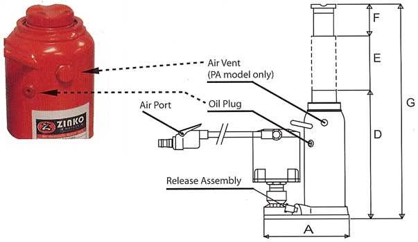
The mechanics of lifting heavy loads rely on a well-engineered system designed to maximize force with minimal effort. At its core, this device consists of several interconnected elements that work together to achieve the required motion and support. These elements ensure stability and precision during the lifting process, allowing for safe and controlled elevation of weighty objects.
Each component within this tool plays a specific role in maintaining the balance and functionality of the entire system. The sturdy base provides support, while the central mechanism ensures smooth movement. Additionally, the operating levers and handles allow for easy manipulation, ensuring the user can apply the necessary pressure with precision.
By exploring the detailed design of this lifting device, we gain a deeper understanding of how each element contributes to the overall efficiency. Recognizing the interaction between these elements is crucial for maintaining and operating the mechanism correctly, ensuring its durability and reliability over time.
Hydraulic Bottle Jack Parts Overview
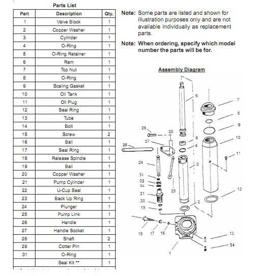
The lifting device consists of several interconnected components, each playing a crucial role in its overall function. These elements work together to create the lifting force necessary to raise and support heavy loads. Understanding the key components and their functions can help users maintain and troubleshoot the equipment effectively.
Main Components and Functions
The device operates through a combination of a pumping mechanism, a support base, and a lifting arm. These parts interact to produce the motion needed for load elevation. The durability and efficiency of these components determine the performance of the tool in various applications.
Table of Key Elements
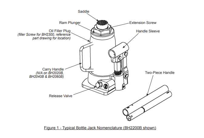
| Component | Function |
|---|---|
| Pumping Mechanism | Creates the force to lift the load. |
| Support Base | Ensures stability during the operation. |
| Lifting Arm | Transfers the force to elevate the object. |
Key Components of a Bottle Jack
The mechanical tool used for lifting heavy objects consists of several crucial elements, each working together to ensure efficient operation. Understanding the main components helps in better maintenance and troubleshooting when needed. These elements support the lifting function, enabling smooth and reliable performance under load.
Main Structure
The main framework serves as the foundation, providing stability and balance during use. This section ensures that the entire unit remains securely positioned while bearing weight, preventing accidents or slips.
Lifting Mechanism
The internal system responsible for raising and lowering is driven by a series of actions that generate upward force. It allows precise control over the movement, ensuring smooth elevation and lowering of objects without abrupt shifts.
| Component | Function |
|---|---|
| Base | Provides support and stability |
| Piston | Moves vertically to lift the load |
| Release Valve | Controls the descent of the lifted object |
| Handle | Used to operate the lifting mechanism |
Understanding the Jack’s Hydraulic System
The lifting mechanism operates through a fluid-based power transfer, allowing substantial weight to be lifted with minimal force. This system relies on the displacement of liquid to generate the necessary pressure for raising and lowering heavy loads.
Main Components Involved
- Piston Assembly: This element is crucial for movement, pushing fluid to create the lifting force.
- Release Valve: Allows control over the lowering process by managing the flow of liquid back into the chamber.
- Reservoir: A container where the liquid is stored when not in use.
How Fluid Motion Works
- When the pump is activated, fluid is pushed from the reservoir into the main cylinder.
- As the fluid fills the cylinder, it exerts pressure, moving the piston upward and lifting the load.
- Releasing the valve redirects the liquid back, lowering the load smoothly and safely.
Pump Mechanism and Its Function
The pump mechanism is the core of this lifting tool, designed to convert manual effort into powerful force. Through a simple series of movements, this component enables the transformation of energy, driving the lifting action. Understanding its function is key to appreciating how this system operates smoothly and efficiently, providing reliable support in heavy lifting tasks.
How the Pump Works
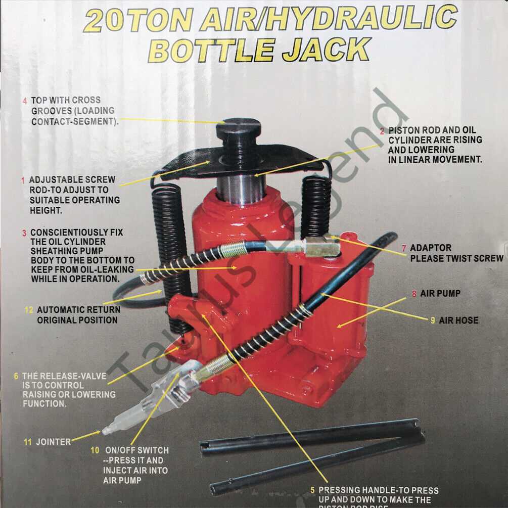
The pump works by creating pressure through repeated strokes. As the lever is engaged, fluid is drawn into the chamber, and with each pump, it pushes the fluid into the system, generating enough power to raise heavy loads. This action relies on precision and consistency, ensuring safe and controlled movements.
Main Components of the Pump
The pump consists of a chamber, lever, and a series of valves that regulate the flow of fluid. The valves ensure that the fluid moves in the right direction, while the lever gives the user control over the force applied. Together, these parts form a cohesive system, maximizing efficiency and ease of use during operation.
Role of the Release Valve in Lifting
The release valve plays a crucial role in controlling the lifting process. It manages the movement of fluid within the system, ensuring smooth and safe operation when raising or lowering loads. By adjusting the valve, the user can regulate pressure and control the height at which objects are elevated. Proper use of the release valve prevents overloading and ensures that the system operates efficiently.
Functions of the Release Valve
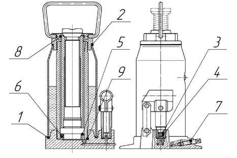
- Pressure Control: The valve allows for precise management of the pressure, ensuring that the lifting mechanism performs optimally without excessive strain.
- Lowering Control: When engaged, the valve releases fluid at a controlled rate, allowing for smooth lowering of the load without abrupt movements.
Ensuring Proper Operation
- Always inspect the valve for any signs of wear or obstruction before using the system.
- Ensure the valve is properly adjusted before lifting, as improper settings can lead to uneven or unsafe movements.
Importance of the Ram in Load Bearing
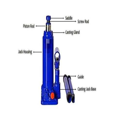
The ram plays a crucial role in supporting and lifting heavy objects, transferring force to maintain stability during the elevation process. It ensures the smooth and even distribution of pressure, allowing the equipment to perform its function efficiently without imbalances. Without the ram, the load-bearing process would become unstable, increasing the risk of failure and causing potential damage.
Load Distribution Efficiency
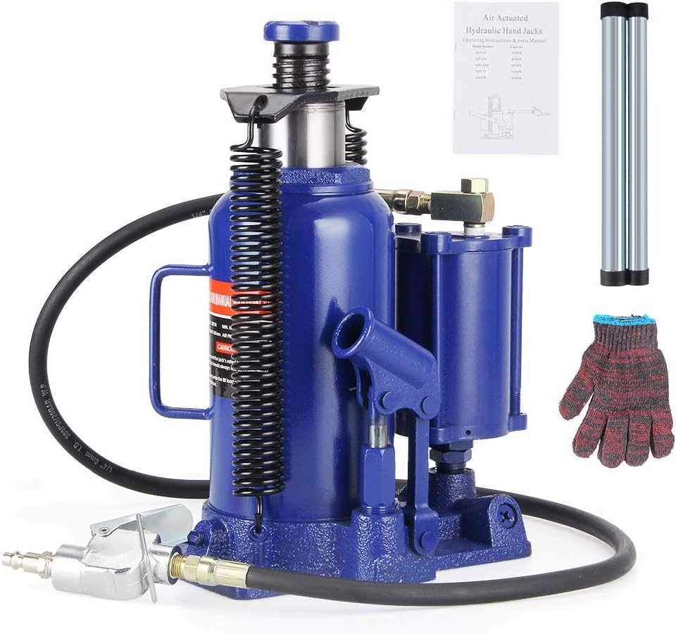
The ram is responsible for evenly distributing the force applied, ensuring that the load is raised without tilting or slipping. This balance allows the equipment to maintain a firm grip on the object, preventing accidents and ensuring safety during operation. The ram’s strength and durability directly influence how efficiently the weight is managed.
| Ram Feature | Impact on Load Bearing |
|---|---|
| Material Strength | Provides resilience under heavy weights |
| Stroke Length | Determines maximum height achievable |
Base Structure and Stability Features
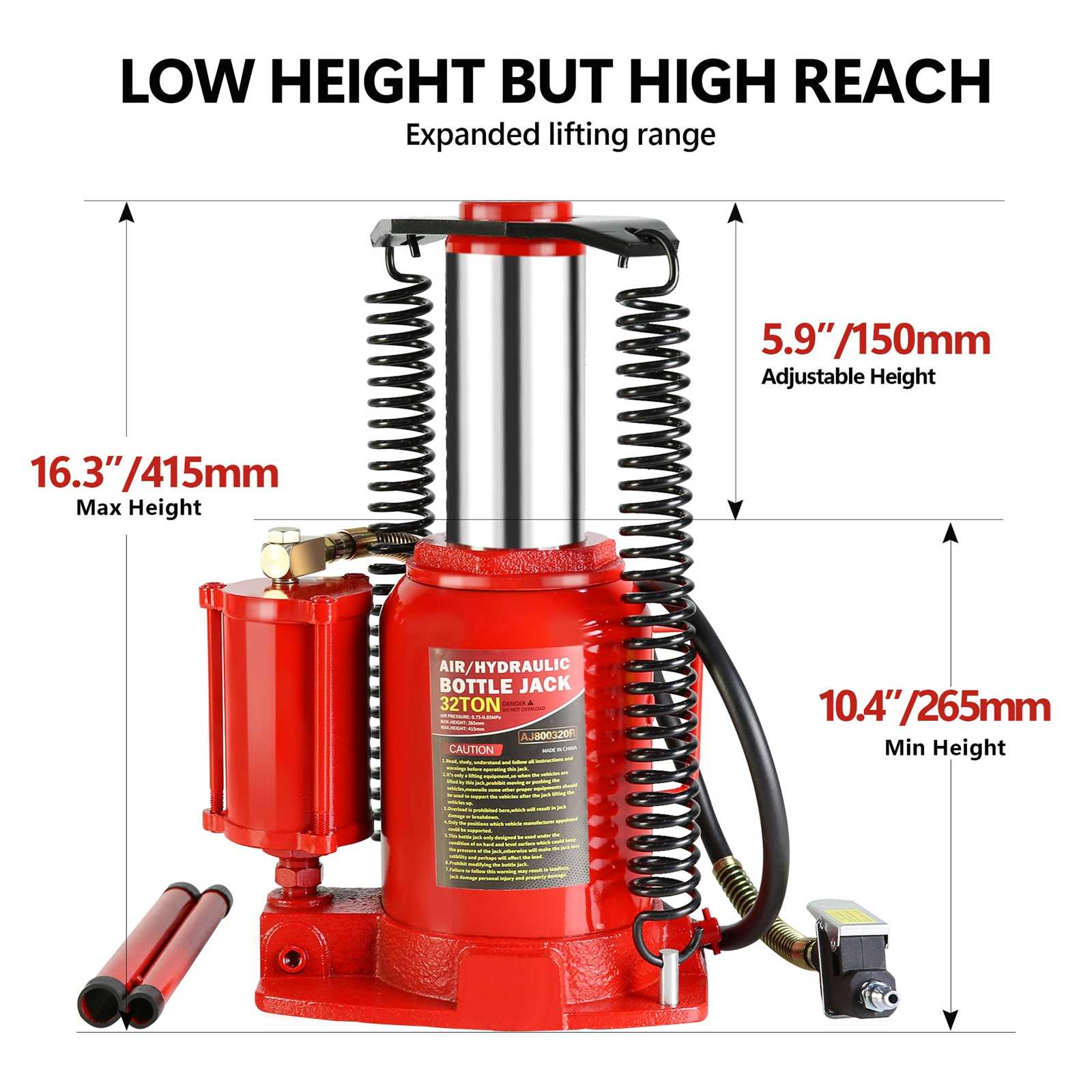
The foundation of this tool’s design is engineered to provide optimal support and reliability during use. Its structure ensures even distribution of force, contributing to a secure and stable experience when applying load. This section explores the key elements that enhance stability and maintain balance, preventing unwanted shifts during operation.
Key Components of the Base
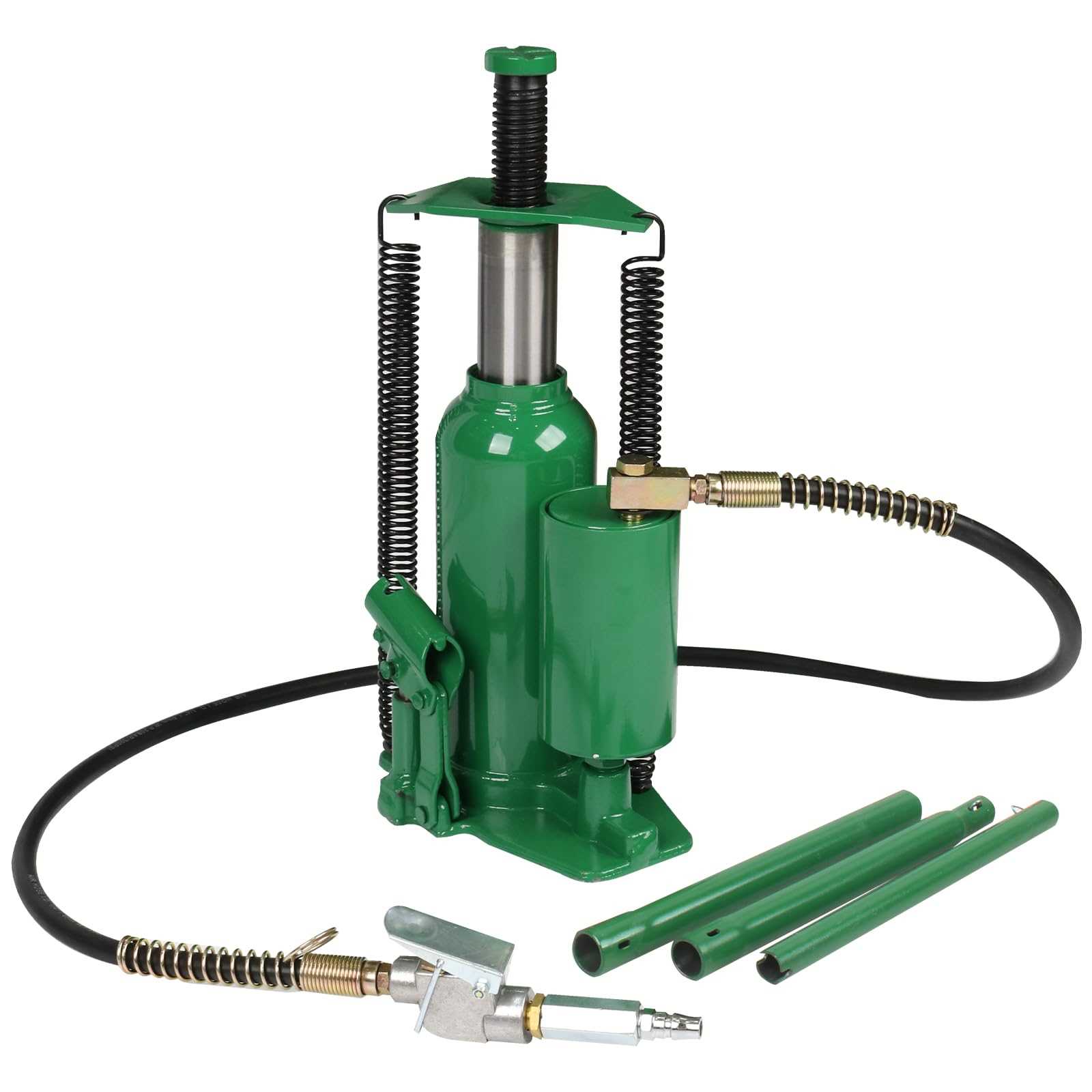
- Reinforced Frame: The core framework is constructed from durable materials to withstand high pressure and resist deformation.
- Wide Support Platform: A broad base ensures greater contact with the ground, minimizing the risk of tipping or instability.
Stability Enhancements
- Non-Slip Surface: The bottom is often equipped with non-slip elements to maintain a firm grip on various surfaces.
- Weight Distribution Design: The design is optimized to evenly spread the load, ensuring consistent and balanced performance.
Oil Chamber and Fluid Maintenance
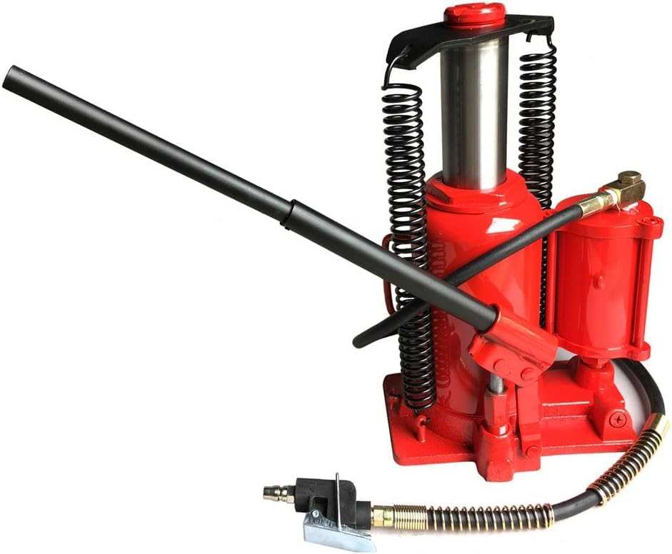
The oil chamber plays a crucial role in ensuring smooth and efficient operation of lifting equipment. Proper maintenance of the fluid inside this chamber is essential for performance and longevity. Over time, the fluid may degrade or become contaminated, which can affect the overall functionality. Regular inspection and timely fluid replacement will help in maintaining optimal efficiency.
Here is a simple guide to managing the fluid in the chamber:
| Step | Action | Frequency |
|---|---|---|
| 1 | Check fluid levels | Every 6 months |
| 2 | Inspect for any leaks | Monthly |
| 3 | Replace old or contaminated fluid | Annually or as needed |
Regular attention to the fluid condition and ensuring the chamber remains properly sealed can prevent common operational issues and extend the lifespan of the lifting device.
Common Seal Types in Bottle Jacks
Seals play a vital role in the functionality of lifting devices, ensuring the effective containment of fluids and preventing leaks. Various types of seals are employed in these mechanisms to enhance performance and durability.
O-Rings are one of the most frequently used sealing solutions due to their versatility and reliability. Made from elastomeric materials, they provide a tight seal and can accommodate various pressure levels.
U-Cups are another popular option, designed to handle high-pressure environments. Their unique shape allows for efficient sealing while maintaining minimal friction during operation.
Flat Seals, often made from rubber or composite materials, are utilized in applications where a larger sealing surface is necessary. They effectively distribute pressure and provide a robust barrier against fluid escape.
Backup Rings are used in conjunction with other seal types to enhance longevity and performance. They prevent extrusion and help maintain the integrity of the primary seal, particularly in dynamic applications.
Understanding these common sealing options can aid in selecting the right components for optimal performance and reliability in lifting applications.
Handle and Pump Lever Design
The handle and lever system plays a crucial role in the functionality and efficiency of lifting mechanisms. This section explores the innovative designs that enhance user experience and operational performance.
Typically, the handle is designed for comfort and ease of use, allowing for a firm grip during operation. The lever, connected to the lifting mechanism, amplifies the user’s input force, making lifting heavy objects more manageable. Various configurations exist to suit different applications and preferences.
| Feature | Description |
|---|---|
| Ergonomic Handle | Designed to reduce strain and improve grip, ensuring comfort during prolonged use. |
| Lever Length | Longer levers provide greater mechanical advantage, allowing for easier lifting of heavier loads. |
| Material Quality | High-strength materials enhance durability and resistance to wear, contributing to longevity. |
| Pivot Point | Strategically located to maximize efficiency and minimize required effort for operation. |
Understanding these design elements is essential for selecting the right equipment for specific lifting tasks, ensuring both safety and effectiveness.
Inspecting Safety Features of the Jack
Ensuring the reliability of lifting equipment is crucial for safe operation. Evaluating the safety elements is essential to prevent accidents and to maintain optimal functionality. This process involves examining various components that contribute to the overall security and effectiveness of the mechanism.
Key Components to Check
Regular inspection of specific features helps in identifying potential risks. Below are the main elements to focus on during the evaluation:
| Component | Function | Inspection Tips |
|---|---|---|
| Overload Valve | Prevents excessive weight from being lifted. | Ensure it opens at the specified pressure limit. |
| Release Mechanism | Controls the descent of the lifted load. | Test for smooth operation and responsiveness. |
| Base Stability | Provides a secure foundation during use. | Check for any cracks or deformities. |
| Safety Lock | Locks the load in place to prevent accidental release. | Verify proper engagement and disengagement. |
Importance of Routine Inspections
Conducting regular assessments not only enhances safety but also prolongs the lifespan of the equipment. Awareness of potential faults and timely maintenance can avert mishaps, making thorough checks an indispensable practice.