Ultimate Guide to Understanding Mb Parts Diagram

Exploring the intricate layout of your vehicle’s system reveals the interconnections that contribute to its overall functionality. By examining each element, one can gain insight into how various sections work together harmoniously.
Analyzing these essential elements not only enhances your knowledge but also assists in maintaining and optimizing performance. Whether you’re a seasoned mechanic or a curious owner, understanding these components is crucial.
Diving deeper into the specifics can uncover nuances that improve your driving experience. Knowing the roles of different segments allows for informed decisions regarding repairs and upgrades, ensuring your vehicle remains in peak condition.
Understanding the Mb Parts Diagram
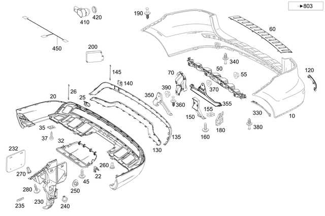
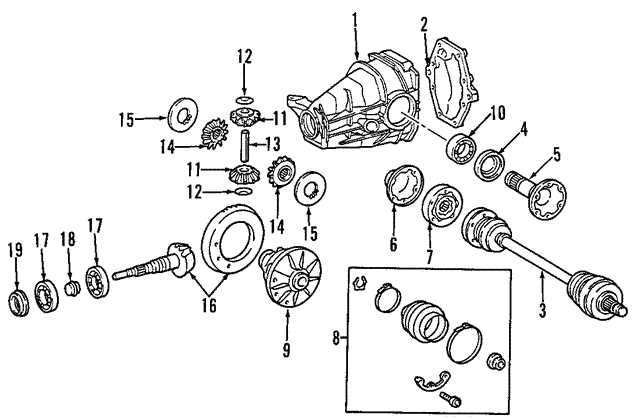
This section explores the intricacies of the Mb schematic representation, focusing on how various components interact and function together. By examining this visual guide, one can gain insights into the overall structure and relationships within the system.
Key Components of the Schematic

At the core of the representation lies a series of interconnected elements that serve distinct purposes. Each element contributes to the system’s functionality, highlighting the importance of understanding their individual roles and how they cooperate to achieve the desired outcomes.
Benefits of Familiarity
Grasping the layout and organization of this schematic can significantly enhance troubleshooting and maintenance efforts. A deeper understanding fosters more effective decision-making and promotes optimal performance in various applications.
Purpose of the Mb Parts Diagram
The primary function of this visual representation is to enhance understanding of the intricate components and their interactions within the system. By breaking down complex assemblies into manageable segments, users can more easily navigate and identify each element’s role and significance.
Facilitating Maintenance and Repair
One of the ultimate advantages of this schematic is its ability to streamline maintenance processes. Technicians can quickly locate specific elements, making repairs and replacements more efficient.
Supporting Assembly and Design

This illustration also aids in the design and assembly phases, offering a clear blueprint for constructing or modifying the system. It serves as a reference for both novice and experienced engineers.
| Function | Description |
|---|---|
| Maintenance | Streamlines identification and replacement of components. |
| Design | Provides a clear reference for assembly and modifications. |
| Education | Aids in understanding the system’s architecture and function. |
Key Components Illustrated in Diagrams
Visual representations play a crucial role in understanding the intricate structures and functionalities of various systems. By providing clear depictions of essential elements, these illustrations facilitate a deeper comprehension of how each component interacts within a larger framework. This approach not only enhances learning but also aids in troubleshooting and maintenance tasks.
Understanding Functional Elements
Each essential component can be showcased to highlight its unique role and interconnectivity. These visuals serve as valuable tools for both professionals and enthusiasts, allowing for an easier grasp of complex systems. Whether for educational purposes or practical applications, such representations help demystify the intricate workings of technology.
Importance of Clarity and Detail
Clear and detailed visuals are vital for effective communication of technical information. They allow users to quickly identify crucial elements and their functions, fostering a more intuitive understanding of the overall system. Such clarity ensures that even those with limited expertise can engage with and appreciate the intricacies involved.
How to Read Mb Parts Diagrams
Understanding visual representations of components is essential for effective maintenance and repair. These illustrations serve as guides, providing insight into the arrangement and relationships of various elements. Mastering this skill enhances both efficiency and accuracy during any task.
Familiarizing Yourself with the Key Symbols
Begin by identifying common symbols used in these illustrations. Each representation conveys specific information about the function or type of the component. Pay attention to these icons, as they will help you navigate through the visual information seamlessly.
Interpreting Connections and Relationships
Next, focus on how the elements connect with one another. Lines and arrows often indicate interactions and flows between parts. Understanding these connections is crucial for grasping the overall operation of the system, allowing you to diagnose issues effectively.
Common Issues Identified by Diagrams
Visual representations play a crucial role in identifying various challenges within complex systems. By breaking down components and their interactions, these illustrations help users quickly pinpoint problems that may not be immediately apparent. This section explores frequent difficulties revealed through such visual tools.
- Connection Failures: Poor links between elements can lead to malfunctioning systems. Common signs include:
- Inconsistent performance
- Unexpected shutdowns
- Component Misplacement: Errors in positioning can disrupt functionality. Look for:
- Physical damage
- Improper alignment
- Wiring Issues: Incorrect or damaged connections often cause significant problems. Symptoms include:
- Overheating
- Intermittent failures
- Incompatibility: Using mismatched elements can lead to system inefficiencies. Indicators may be:
- Frequent errors
- Reduced lifespan of components
Understanding these common challenges allows for timely intervention and effective maintenance, ultimately enhancing the longevity and reliability of the entire system.
Comparing Different Models’ Diagrams
Understanding the variations between various designs can enhance one’s grasp of their functionalities and features. Each model presents unique characteristics that serve specific purposes, highlighting advancements and differences in technology.
| Model | Key Features | Compatibility |
|---|---|---|
| Model A | Advanced cooling system, optimized layout | Compatible with versions 1.0 – 1.5 |
| Model B | Enhanced durability, compact design | Compatible with versions 2.0 – 2.3 |
| Model C | High performance, energy-efficient | Compatible with versions 3.0 – 3.5 |
By delving into these distinctions, one can identify the ultimate choice for specific needs and preferences.
Benefits of Using Parts Diagrams
Utilizing visual representations of components provides numerous advantages for both professionals and enthusiasts. These graphical tools enhance understanding and facilitate communication, streamlining various processes in maintenance and assembly.
- Improved Clarity: Visual aids simplify complex information, making it easier to grasp intricate relationships between different elements.
- Enhanced Communication: Clear illustrations bridge the gap between technical jargon and user understanding, promoting effective collaboration among team members.
- Efficient Troubleshooting: When issues arise, these visuals allow for quick identification of problematic areas, reducing downtime and facilitating faster resolutions.
- Accurate Assembly: Step-by-step visual guides ensure correct placement and orientation of components, minimizing the risk of errors during the assembly process.
- Comprehensive Documentation: These visuals serve as valuable reference materials, providing a detailed overview of structures and allowing for easier updates and revisions.
Incorporating such illustrations into workflows not only boosts productivity but also enhances the overall quality of work, making them an indispensable resource in various fields.
Tips for Accurate Diagram Interpretation
Understanding complex visual representations is essential for effective communication in technical fields. By honing your skills in analysis, you can enhance comprehension and application of the information presented. Here are some strategies to improve your interpretation abilities.
Familiarize Yourself with Symbols
Every visual representation has its own set of symbols and conventions. Take time to learn these elements, as they convey critical information. Being aware of what each symbol means will greatly facilitate your understanding.
Follow Logical Connections
Identifying the relationships between various elements is crucial. Pay attention to how different components are interconnected, as this will provide insights into their functionality and role within the larger system.
Where to Find Mb Parts Diagrams
Locating detailed illustrations for your Mb model can significantly enhance your understanding and maintenance efforts. These visuals serve as essential tools for identifying components and ensuring proper assembly.
Online resources are abundant. Websites dedicated to automotive repair often feature comprehensive collections. Forums and community groups can also provide valuable insights and shared resources from fellow enthusiasts.
For the ultimate reference, consider manufacturer websites. They typically offer official resources that are accurate and up-to-date. Local dealerships may also have printed materials or can assist in accessing specific illustrations.
Don’t overlook repair manuals, which can be found in bookstores or online marketplaces. These often include detailed visuals that cater to various models.
Utilizing these avenues will help you delve into the intricacies of your Mb vehicle, ensuring that you have the right information at your fingertips.
Integration with Repair Manuals
Integrating technical guides with comprehensive documentation enhances the overall repair experience. This synergy provides users with valuable insights and step-by-step instructions that simplify the troubleshooting and maintenance processes.
Benefits of Integration
- Streamlined access to essential information
- Improved clarity through visual aids
- Time-saving features for efficient repairs
Key Features to Consider
- Detailed illustrations that complement textual instructions
- Interactive elements for user engagement
- Search functionality for quick navigation
Combining these resources empowers users to tackle repairs confidently and effectively, ensuring a smoother workflow and better outcomes.
Technological Advances in Diagram Creation
The evolution of tools for visual representation has transformed how complex information is communicated. Innovations in software and technology have significantly enhanced the clarity, accessibility, and interactivity of these visual aids.
Key Innovations
- Cloud-based platforms for real-time collaboration
- AI-driven suggestions for layout and design
- Integration with other software for seamless data transfer
Impact on Industries
- Education: Enhanced learning through interactive visuals
- Engineering: Streamlined project planning and communication
- Marketing: Improved presentation of ideas and concepts
Case Studies: Successful Repairs Using Diagrams
This section explores various instances where visual guides have played a crucial role in the repair and restoration processes. By analyzing these successful cases, we can understand the significance of having clear and organized visual representations when tackling complex tasks.
-
Automotive Repairs
In one case, a mechanic utilized an intricate visual representation to successfully restore an engine. The clarity provided by the guide enabled the technician to identify and fix issues efficiently.
-
Electronics Restoration
A hobbyist managed to repair a vintage radio by referring to a detailed schematic. This visual aid helped them trace faulty connections, ultimately bringing the device back to life.
-
Home Appliance Fixes
In a home scenario, a homeowner tackled a malfunctioning washing machine by following a visual reference. This approach not only expedited the repair but also empowered them with the knowledge to address future issues.
These examples underscore the ultimate value of employing structured visuals in repair scenarios, enhancing both efficiency and understanding in complex tasks.