Detailed Breakdown of Minn Kota Endura 50 Components
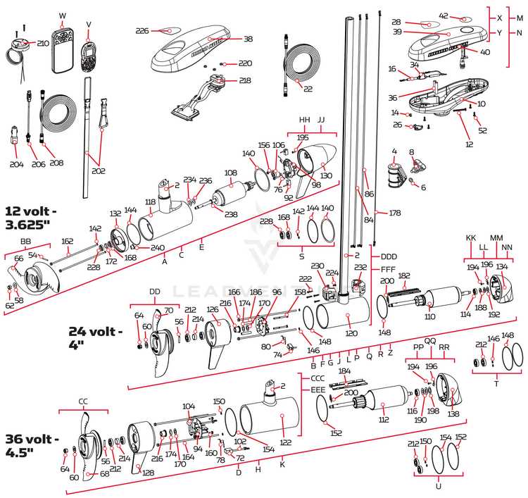
When working with electric propulsion systems for small watercraft, understanding the structure and organization of internal elements is essential. Each component plays a critical role in ensuring efficient operation, from the power source to the control mechanisms. In this guide, we’ll explore how these elements fit together to create a functional and reliable system.
Whether you’re performing routine maintenance or diagnosing potential issues, a clear overview of the various components can help streamline the process. Knowing where each part is located and how it interacts with others will enable you to identify and replace any worn or damaged elements with ease.
In the following sections, we’ll take a closer look at the individual parts, their arrangement, and the overall design, allowing for a deeper understanding of this specific propulsion technology.
Exploring the Minn Kota Endura 50 Structure
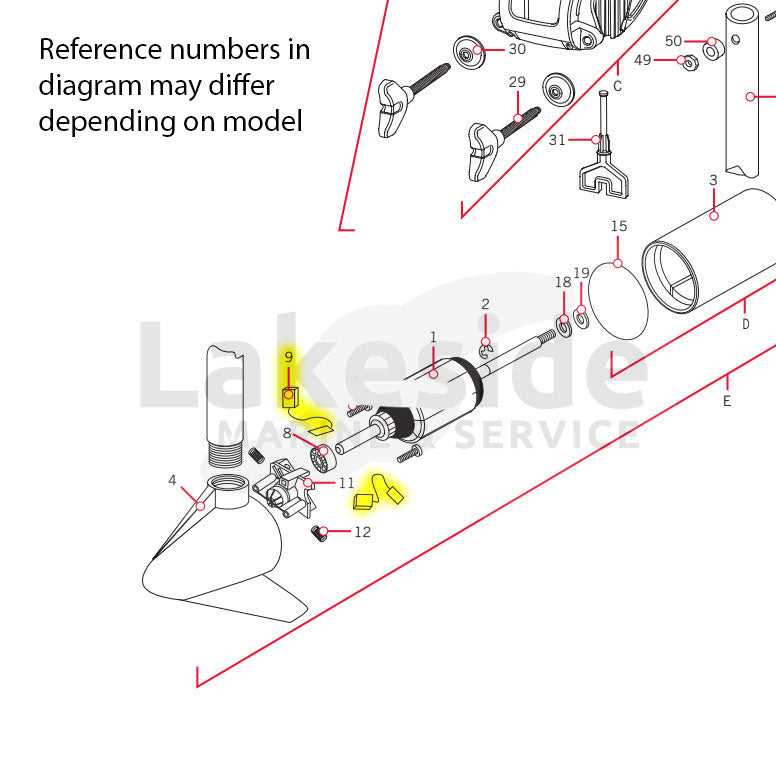
Understanding the design and layout of this trolling motor is essential for those looking to optimize its performance or make repairs. The internal components are carefully arranged to ensure both efficiency and durability, making it a reliable choice for various watercraft. Below, we will examine the key elements that contribute to its overall construction and functionality.
Main Components Overview
- Control Head: The top section houses the controls, allowing users to adjust speed and direction with ease.
- Motor Housing: This part protects the electric motor from external factors like water and debris, ensuring smooth operation.
- Propeller: Located at the lower end, the propeller is designed for maximum thrust while maintaining low energy consumption.
Power and Steering Mechanisms
At the core of the system, the power supply and steering mechanisms work in harmony to provide consistent propulsion. The manual steering system gives precise control over navigation, while the power circuits are designed to deliver optimal current flow to the motor, enhancing overall performance.
- Shaft: This vertical rod connects the motor to the steering controls, offering both durability and flexibility in different water conditions.
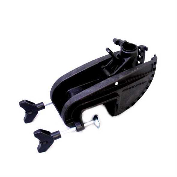
- Mounting Bracket: This allows secure attachment to the boat, ensuring stability even at high speeds.
Key Components of the Motor Assembly

The assembly of this motor consists of several essential elements that work together to ensure smooth operation and durability. Understanding how these components interact is crucial for maintenance and repair tasks. Below is an outline of the core elements involved in the functioning of the motor system.
- Propeller: This is the part responsible for generating thrust, propelling the system forward or backward. It attaches to the motor shaft and rotates when powered.
- Motor Housing: The outer shell that encases the mechanical parts, providing protection from external factors like water and debris.
- Control Handle: This part allows the operator to manage speed and direction, offering a simple interface for precise control.
- Battery Cables: Wires that connect the motor to the power source, delivering the required electrical current to activate the motor.
- Shaft: The long rod that connects the motor to the propeller, ensuring the transfer of energy from the motor to the water.
Each of these components plays a vital role in the overall efficiency and performance of the motor. Proper maintenance of each part is key to extending the operational lifespan of the system.
Understanding the Thrust System Mechanics
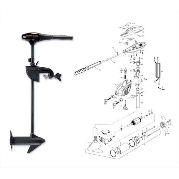
The mechanics behind the force generation in water propulsion systems play a crucial role in determining efficiency and performance. These systems rely on the interaction of various components working together to produce the necessary force for movement through water. Understanding how these elements are structured and how they function is essential for optimizing and maintaining peak performance over time.
| Component | Function |
|---|---|
| Propeller | Converts rotational energy into thrust, pushing the vessel forward. |
| Motor | Supplies power to the propeller, ensuring continuous motion. |
| Control Unit | Regulates speed and direction by adjusting power flow to the motor. |
| Drive Shaft | Transfers mechanical energy from the motor to the propeller. |
Each component plays a vital role in generating the force needed to move a boat through the water. The balance between power, efficiency, and control determines the overall performance of the propulsion system.
Propeller Design and Functionality Overview
The design of a propeller plays a crucial role in ensuring efficient movement through the water. Its primary function is to convert rotational power into thrust, enabling smooth and effective propulsion. Key factors such as the number of blades, blade shape, and material composition determine how well it can perform under various conditions. Understanding these elements can provide insight into optimizing performance for different watercraft.
| Aspect | Description |
|---|---|
| Blade Count | Propellers typically have two or more blades. More blades generally offer smoother operation but can decrease efficiency at higher speeds. |
| Blade Shape | Curved blades are designed for better grip in the water, while straighter blades may provide faster acceleration and top speed. |
| Material | Propellers can be made from materials such as aluminum or composite for different durability and performance levels. Metal is usually stronger, while composites can offer lighter weight. |
| Pitch | Pitch refers to the angle of the blades, affecting the distance traveled per rotation. Higher pitch is better for speed, while lower pitch improves control at slower speeds. |
Handle and Control Features Breakdown
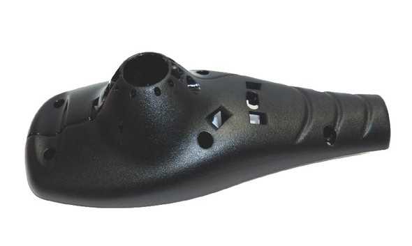
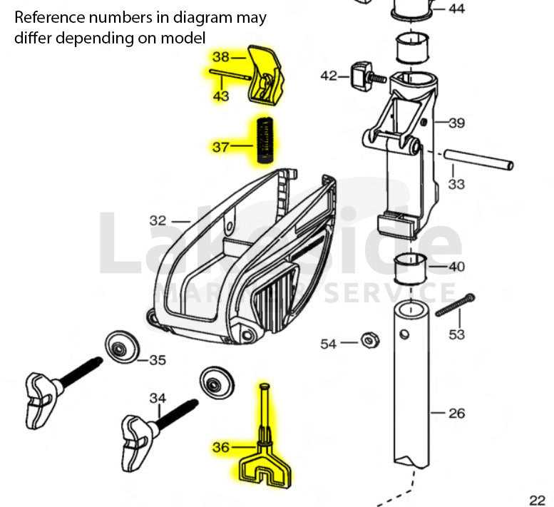
The steering system and control interface of this motor model offer an intuitive experience, designed for precise navigation and easy adjustments during use. Understanding the key components will help you get the most out of the system, ensuring smooth operation and reliable performance on the water.
- Ergonomic Grip: The handle is crafted to provide comfort, allowing for extended periods of use without fatigue.
- Variable Speed Control: The speed adjustment feature enables precise control over your vessel’s movement, giving you flexibility in different water conditions.
- Forward and Reverse Options: Effortless switching between forward and reverse makes maneuvering simple, even in tight spaces.
- Telescopic Function: The extendable handle allows for better reach, offering enhanced control over navigation when needed.
- Durable Construction: Built with robust materials, the control handle is designed to withstand tough conditions and frequent use.
This system’s combination of comfort, flexibility, and durability ensures that you can navigate confidently, regardless of your skill level or water environment.
Electrical Wiring and Connections Guide
This section provides a comprehensive overview of the electrical circuitry and connection methods necessary for optimal functionality. Understanding how to properly link various components is essential for ensuring efficient performance and safety.
Understanding Circuit Layouts
Effective electrical connections begin with a clear understanding of circuit layouts. Each component plays a critical role in the overall system, and recognizing the relationship between them allows for efficient troubleshooting and maintenance. It is vital to follow specific configurations to prevent issues such as short circuits or power loss.
Safety Precautions
Prior to any wiring or connection work, ensure that safety measures are in place. Disconnect power sources to avoid electrical shock. Use appropriate tools and protective gear to safeguard against potential hazards. Furthermore, always consult manufacturer specifications for recommended practices to maintain optimal performance.
Battery Cables and Power Input
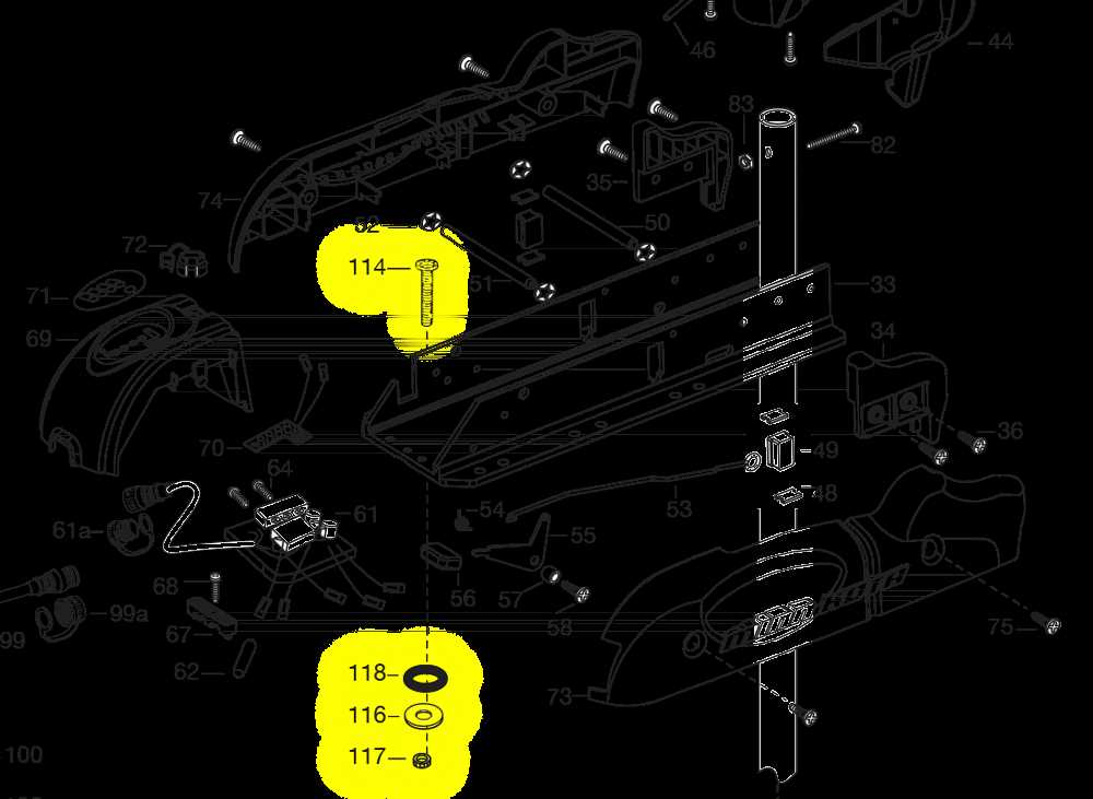
Understanding the significance of power transmission components is essential for optimal performance. The right connections ensure that energy flows efficiently, minimizing losses and maximizing the lifespan of the equipment. Proper selection and maintenance of these components can significantly impact overall functionality.
When it comes to energy transfer, several key elements should be considered:
- Wire Gauge: The thickness of the cables plays a crucial role in determining the current-carrying capacity. Thicker wires reduce resistance and prevent overheating.
- Connector Types: Various connectors are available, each designed for specific applications. Selecting the right type is vital for secure connections and efficient power flow.
- Length of Cables: Longer cables can lead to voltage drop. It’s essential to choose the appropriate length to maintain optimal performance.
Additionally, ensuring that all connections are clean and free from corrosion is important for reliable operation. Regular inspection of these components can prevent unexpected failures and ensure that the system operates smoothly.
Importance of Shaft Length Adjustments
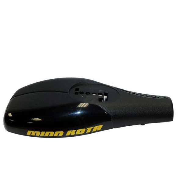
Proper adjustments of the shaft length in motor systems play a crucial role in ensuring optimal performance and efficiency. By customizing the length, users can significantly enhance the functionality of their equipment, ensuring it operates effectively in varying conditions. This practice not only maximizes the effectiveness of the propulsion system but also extends the lifespan of the components involved.
Benefits of Proper Adjustments
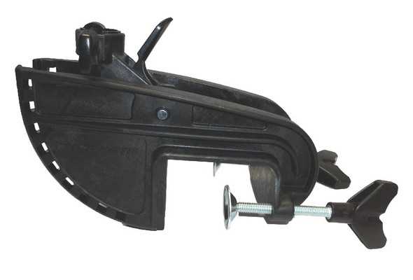
- Improved Efficiency: Tailoring the shaft length can lead to better energy use, resulting in lower operational costs.
- Enhanced Maneuverability: A well-adjusted shaft allows for more responsive handling, particularly in challenging environments.
- Increased Stability: Correct length ensures the motor is optimally positioned, reducing the likelihood of instability during operation.
- Reduced Wear and Tear: Custom length adjustments help minimize unnecessary strain on components, prolonging their life.
Considerations for Adjusting Shaft Length
- Water Conditions: Assessing the typical water depth and environmental factors is essential before making adjustments.
- Type of Vessel: Different crafts may require distinct shaft lengths based on their design and intended use.
- Motor Specifications: Understanding the specifications of the propulsion unit is vital to ensure compatibility and effectiveness.
Steering Mechanism and Maneuverability Insights
This section delves into the intricacies of the steering system and its impact on the agility of watercraft. Understanding how the directional controls interact with the vessel’s structure allows for enhanced navigational capabilities and improved performance on various water surfaces.
Key Components of the Steering System
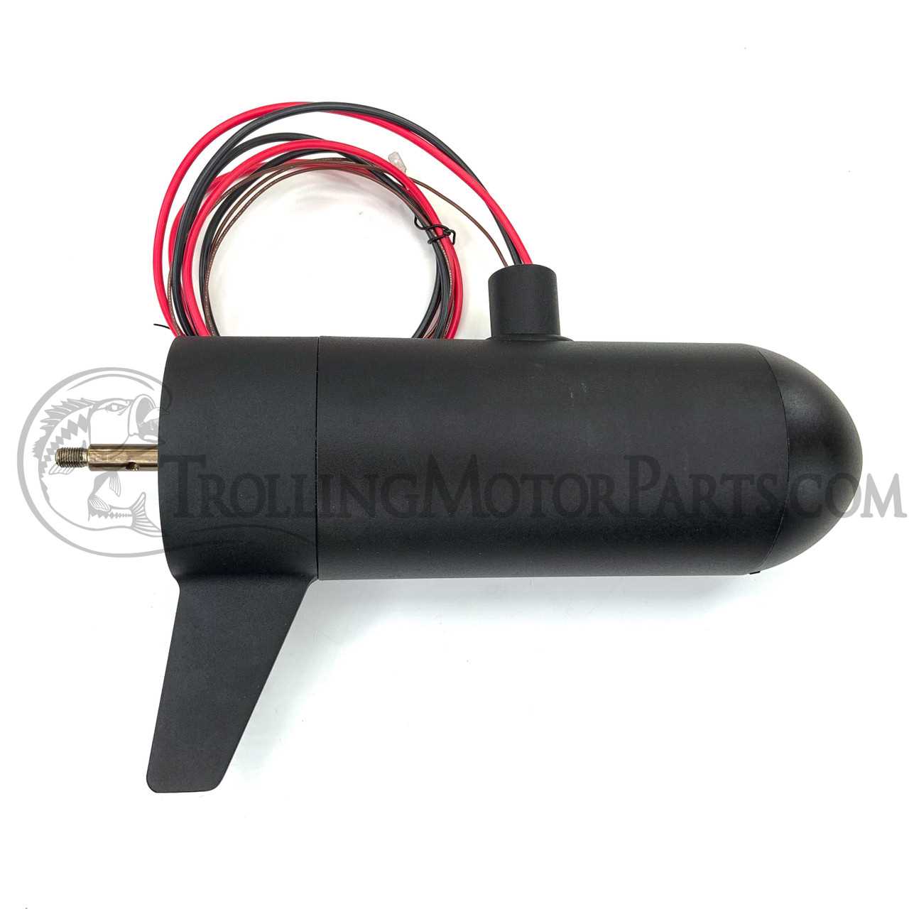
- Tiller Handle: The primary control for steering, allowing the operator to guide the boat’s direction effectively.
- Pivot Point: The fulcrum around which the steering apparatus rotates, playing a crucial role in maneuverability.
- Steering Cable: This component transmits the movement from the handle to the rudder or motor, ensuring precise directional changes.
Maneuverability Considerations
- Response Time: Quick and effective responses to steering inputs significantly enhance handling capabilities.
- Stability: A well-designed steering mechanism contributes to overall stability, especially in turbulent waters.
- Turning Radius: The geometry of the steering system affects how tightly a vessel can turn, impacting navigation in confined spaces.
Mounting System Components and Setup
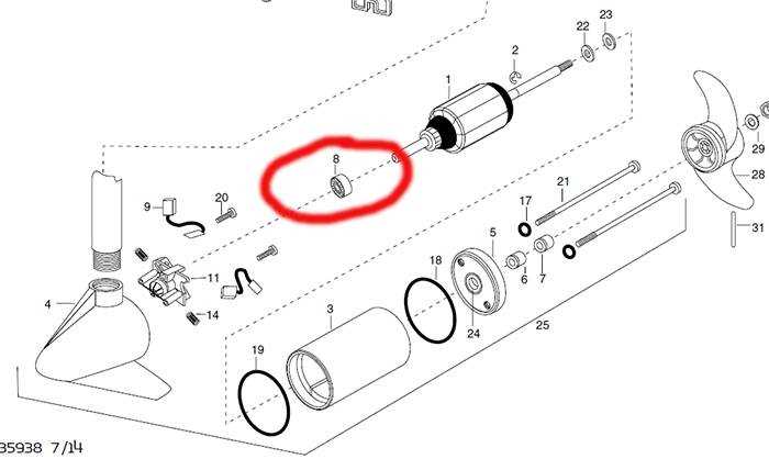
The assembly of the mounting framework is crucial for ensuring stability and ease of use. Properly configured components not only enhance performance but also contribute to the overall safety and functionality of the system. Understanding each element’s role allows users to achieve optimal results in various water conditions.
Key Elements of the Mounting Framework
This section highlights the essential components involved in the mounting setup. Each part serves a specific purpose, ensuring secure attachment and effective operation.
| Component | Description | Function |
|---|---|---|
| Base Plate | A sturdy platform that anchors the system to the boat. | Provides stability and a foundation for the entire assembly. |
| Clamp | A securing device that holds the framework in place. | Ensures that the assembly remains fixed during use. |
| Pivot Arm | A movable component that allows for directional adjustments. | Facilitates easy maneuvering of the assembly for optimal positioning. |
| Mounting Bracket | A support structure that connects the system to the boat. | Enhances the stability of the setup by providing additional support. |
Assembly Instructions
Setting up the framework requires careful attention to detail to ensure all parts are correctly installed. Begin by securing the base plate to the vessel, followed by attaching the clamp. Next, position the pivot arm and finalize the installation with the mounting bracket. Regular checks and adjustments will help maintain an efficient and safe setup.
Troubleshooting Common Motor Issues
Addressing issues with electric propulsion units can be challenging, but understanding common problems can lead to effective solutions. This section outlines frequent complications and provides guidance for diagnosing and resolving them.
Here are some typical issues you may encounter:
- Unit Fails to Start:
- Check the power source; ensure batteries are charged and connections are secure.
- Inspect the wiring for any visible damage or loose connections.
- Intermittent Operation:
- Verify all connections are tight and free from corrosion.
- Consider testing with a different power source to rule out battery issues.
- Unusual Noises:
- Listen for grinding or squealing sounds, which may indicate mechanical wear or obstruction.
- Check for foreign objects lodged in the propeller or housing.
- Overheating:
- Ensure the unit is not overloaded; check the specifications for maximum performance limits.
- Clean the cooling vents and ensure proper air circulation around the motor.
By systematically evaluating these areas, you can diagnose and rectify many common issues associated with electric propulsion systems. Regular maintenance and careful observation can prevent many complications from arising.
Maintenance Tips for Longevity and Efficiency
Regular upkeep is crucial for ensuring the optimal performance and lifespan of your equipment. Implementing a few essential practices can significantly enhance its functionality and reliability, allowing for a smoother experience during usage.
Routine Inspections
- Check for any visible wear and tear on the external components.
- Ensure all connections are secure and free from corrosion.
- Inspect cables for fraying or damage that may affect performance.
Cleaning and Care
- Rinse off any saltwater or debris after each use to prevent buildup.
- Use a soft cloth to wipe down surfaces, avoiding harsh chemicals.
- Periodically lubricate moving parts as recommended to ensure smooth operation.
By adhering to these maintenance tips, you can enhance the efficiency and durability of your equipment, ensuring it remains in peak condition for years to come.