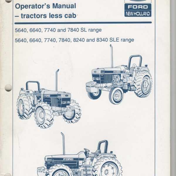
Essential Components Breakdown for Ford 6640 Tractor

Understanding the intricate assembly of mechanical devices used in farming is crucial for ensuring their smooth operation and longevity. Each element within these machines plays a significant role, contributing to the overall efficiency and productivity in various agricultural tasks.
Exploring the interconnected system of these mechanical elements can help operators and technicians identify the optimal way to maintain and repair their equipment. This structured approach not only minimizes downtime but also enhances the lifespan of each component, leading to a more reliable and effective workflow on the field.
Accurate knowledge about the specific configurations and structural arrangements of these machines allows for a proactive approach to upkeep and troubleshooting. It provides a solid foundation for anyone involved in managing or servicing these essential tools, fostering a deeper understanding of how each segment interacts within the larger system.
Engine Components Overview
The internal workings of this machinery’s power unit are comprised of multiple interconnected elements designed to ensure optimal performance. Understanding the function and role of each component can help maintain the system’s efficiency and longevity. This section offers a detailed look into the various elements that play a crucial part in the overall operation of the machine’s engine, emphasizing their interdependence and functionality.
Identifying Key Parts and Functions
Understanding the core components and their roles is crucial for maintaining optimal performance and efficiency in any machinery. This section provides an overview of the essential elements, highlighting their significance and how they contribute to the system’s overall functionality.
- Engine Assembly: Acts as the powerhouse, converting fuel into mechanical energy to drive various operations.
- Hydraulic System: Facilitates movement by transmitting fluid power, crucial for lifting and steering mechanisms.
- Transmission Unit: Ensures the smooth transfer of power from the engine to the wheels, enabling speed adjustments and control.
- Cooling System: Regulates temperature levels, preventing overheating and ensuring consistent operation.
- Electrical Components: Power the lighting, ignition, and other electronic functions, providing essential control and monitoring capabilities.
Recognizing t
Transmission System Layout
The transmission assembly plays a crucial role in converting power from the engine into usable motion, efficiently delivering it to the wheels. Understanding its structure involves examining how each component collaborates to control speed and torque, ensuring smooth operation and performance under various conditions.
Components Overview: The setup includes a series of gears, shafts, and linkages, all meticulously arranged to enable seamless transitions between different speed ranges. These elements are designed to handle different load levels, maximizing efficiency while maintaining durability.
Interaction Between Elements: Key to this arrangement is the synchronization of parts that manage gear changes. The coordination of these elements is essential for reducing wear and enhancing the overall functionality of the system, providing consistent power output.
Understanding Gearbox and Controls
The gearbox and control mechanisms play a crucial role in enhancing the performance of heavy-duty machinery. These components ensure efficient power transmission, providing the necessary precision and control for various operational tasks.
Key Functions of the Gearbox
The gearbox is responsible for managing speed and torque levels, adapting the engine’s power to different mechanical needs. By adjusting the gear ratios, it optimizes the machinery’s output to match specific work conditions, leading to smoother and more efficient operation.
- Speed Regulation: Adjusting speed to suit different activities, ensuring the right balance between power and efficiency.
- Torque Distribution: Managing torque to handle heavy loads without compromising on performance.
Control Systems Overview
Control systems are designed to facilitate easy maneuverability and precise operation of the equipment. They include various levers, switches, and pedals that interact seamlessly with the gearbox to provide responsive
Hydraulic Mechanism Structure
The hydraulic mechanism plays a crucial role in the overall functionality of many mechanical systems, providing the necessary force and control for various operations. Understanding its structure helps in maintaining efficiency and reliability in numerous applications. This section explores the key components and their interconnections within the hydraulic setup.
- Pump Unit: The core of the system that generates fluid movement, converting mechanical energy into hydraulic power to drive different parts.
- Control Valves: These elements regulate the flow and pressure of the hydraulic fluid, ensuring precise movement and operational accuracy.
- Cylinders: Actuators that transform the hydraulic fluid’s pressure into mechanical force, enabling movement of connected elements.
- Reservoir: A storage unit that holds the hydraulic fluid, maintaining the necessary supply for continuous system performance.
- Filters: These components purify the fluid, preventing contaminants from entering the system and ensuring smooth operation.
Each of these components works in
Exploring Pump and Valve Connections
This section delves into the intricate relationships between hydraulic components, emphasizing the significance of effective linkage for optimal performance. Understanding these connections is crucial for maintaining functionality and efficiency in machinery that relies on fluid dynamics.
Key Components of Hydraulic Systems

Hydraulic systems comprise various elements that work together to facilitate fluid movement. Pumps are essential for generating pressure, while valves regulate flow and direct hydraulic fluid to the appropriate circuits. This synergy ensures smooth operation and reliable performance in various applications.
Understanding Connection Types
The connections between pumps and valves can vary based on the design and function of the system. Common connection types include threaded, flanged, and quick-disconnect fittings, each offering distinct advantages in terms of installation, maintenance, and adaptability.
| Connection Type | Description | Advantages |
|---|---|---|
| Threaded | Utilizes threads for secure attachment. | Reliable seal; easy to install. |
| Flanged | Features a flat surface with bolt holes for mounting. | Strong connection; allows for easy disassembly. |
| Quick-Disconnect | Allows for rapid connection and disconnection. | Convenient for frequent maintenance; minimizes downtime. |
Electrical Circuit Arrangement
The organization of electrical connections within machinery plays a crucial role in ensuring efficient operation and functionality. A well-designed circuit layout not only facilitates the smooth transmission of power but also enhances the safety and reliability of the equipment.
In this context, various components such as switches, connectors, and sensors are strategically positioned to create an effective network. Each element serves a specific purpose, contributing to the overall performance and responsiveness of the system. Proper arrangement minimizes the risk of electrical faults and simplifies maintenance procedures, allowing for quick identification and resolution of issues.
Understanding the intricacies of the electrical arrangement aids in troubleshooting and optimizing the machinery’s performance. By analyzing the configuration, operators can ensure that all electrical pathways are functioning correctly, thereby maximizing efficiency and prolonging the lifespan of the equipment.
Analyzing Battery and Wiring Routes
This section focuses on the examination of power sources and electrical pathways within a machinery system. Understanding how these components interact is crucial for ensuring optimal performance and reliability.
Battery placement is a key factor that influences the efficiency of electrical flow. Proper positioning not only facilitates easy access for maintenance but also minimizes the risk of potential hazards caused by incorrect installations. It is essential to evaluate the surrounding areas for sufficient ventilation and protection from environmental factors.
Wiring routes play a vital role in the overall functionality of the system. Analyzing these pathways helps identify any possible points of wear or damage that could lead to malfunctions. Ensuring secure connections and protective coverings for wires is fundamental in maintaining the integrity of the electrical circuit.
By systematically mapping out these elements, operators can make informed decisions regarding upgrades or repairs, ultimately enhancing the longevity and effectiveness of the entire system.
Cooling System Configuration
The cooling system is a crucial component of any heavy machinery, ensuring optimal operating temperatures during various tasks. Its configuration directly influences the efficiency and longevity of the engine, preventing overheating and potential damage. Understanding the layout and functioning of this system can significantly enhance performance and maintenance practices.
Key Components
The primary elements of the cooling system include the radiator, water pump, thermostat, and hoses. The radiator dissipates heat from the coolant, while the water pump circulates the coolant through the engine and back to the radiator. The thermostat regulates the flow of coolant based on the engine’s temperature, ensuring that it operates within the optimal range. Additionally, durable hoses connect these components, facilitating the smooth flow of coolant throughout the system.
Maintenance Considerations
Regular inspection and maintenance of the cooling system are essential for preventing overheating issues. Checking the coolant level, examining hoses for leaks, and ensuring the radiator is free from obstructions are vital practices. Additionally, flushing the system periodically can help remove debris and prevent corrosion, ensuring efficient heat dissipation and extending the lifespan of the machinery.
Mapping Radiator and Hose Placement
Understanding the configuration of cooling components is essential for maintaining optimal performance in agricultural machinery. Proper positioning of the heat exchanger and associated tubing ensures efficient coolant circulation, which is critical for preventing overheating during operation.
Component Overview
In this section, we will explore the key elements involved in the placement of the heat exchanger and the related hoses. Key components include:
- Heat exchanger
- Upper and lower coolant hoses
- Temperature sensors
- Connecting clamps and fittings
Placement Guidelines
When arranging the cooling system, it is crucial to adhere to the following guidelines:
- Ensure the heat exchanger is securely mounted in a location that allows for optimal airflow.
- Route the upper hose from the engine to the top inlet of the heat exchanger, avoiding sharp bends that may restrict flow.
- Connect the lower hose to the outlet of the heat exchanger, leading back to the engine for effective coolant return.
- Regularly inspect hoses for wear and damage, replacing any that show signs of deterioration.
By following these principles, operators can maintain the efficiency of their cooling systems, prolonging the lifespan of their machinery.
Fuel Delivery Framework

The system responsible for transporting energy sources to the engine plays a crucial role in the overall functionality of any heavy machinery. A well-designed framework ensures optimal performance, efficiency, and reliability, allowing the equipment to operate seamlessly in various conditions. Understanding the components and their interactions is essential for maintaining and enhancing the functionality of this vital system.
Key Components
This framework comprises several critical elements that work together to facilitate the movement of fuel from the storage to the engine. Each component has a specific function that contributes to the efficiency of the entire system.
| Component | Function |
|---|---|
| Fuel Tank | Stores the energy source for the engine. |
| Fuel Pump | Transfers fuel from the tank to the engine. |
| Fuel Filter | Removes impurities and contaminants from the fuel. |
| Fuel Lines | Conduits that transport fuel between components. |
| Injectors | Deliver precise amounts of fuel into the combustion chamber. |
Maintenance Considerations
Regular inspections and maintenance of the fuel delivery framework are essential to ensure its longevity and efficiency. Checking for leaks, replacing filters, and monitoring the condition of pumps and injectors are vital practices that can prevent costly repairs and downtime.
Details on Tank and Line Setup
Understanding the configuration of fuel storage and distribution systems is crucial for optimal machinery performance. This section delves into the intricacies of assembling and connecting the necessary components to ensure efficient operation.
The tank serves as the primary reservoir, and its placement must allow for seamless access and maintenance. When installing the storage unit, ensure it is securely mounted to prevent any movement or vibrations that could lead to leaks. The use of quality materials is essential for durability and reliability.
Connections between the tank and fuel lines are pivotal. Utilizing appropriate fittings will minimize the risk of fuel leakage and enhance the integrity of the system. It’s vital to inspect these connections regularly for any signs of wear or damage.
Proper routing of the lines is equally important. Avoid sharp bends or kinks, as these can restrict flow and lead to pressure build-up. Make sure that the lines are supported adequately to prevent any undue stress on the fittings and connections.
Regular maintenance checks will help identify any issues before they escalate, ensuring the entire setup functions smoothly and efficiently.
Brake Assembly Design
The brake assembly is a crucial component in ensuring the safety and efficiency of various machinery. Its design must facilitate optimal performance, providing reliable stopping power while maintaining durability and ease of maintenance. Understanding the fundamental elements involved in this assembly is essential for achieving desired operational standards.
Key components of the brake assembly include:
- Brake Pads: These create friction against the braking surface, converting kinetic energy into heat.
- Brake Discs: Attached to the wheel, these provide the surface against which the pads press.
- Calipers: These house the brake pads and are responsible for applying pressure during braking.
- Brake Lines: These carry hydraulic fluid to the calipers, facilitating the braking action.
The effectiveness of the brake assembly is influenced by factors such as material quality, design precision, and maintenance practices. Proper installation and regular inspections contribute significantly to the longevity and reliability of the braking system.