Millermatic 185 Parts Diagram Overview
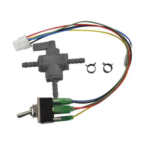
The structure and organization of internal elements in various industrial tools are essential for maintaining functionality and ensuring longevity. Understanding how these components fit together can greatly aid in troubleshooting and routine maintenance.
In this guide, we explore the arrangement of various sections within a common welding device. By grasping how each unit is positioned and connected, you can gain a clearer picture of its overall operation and potential areas for repair.
This detailed look into the assembly layout provides insights for those seeking to repair, upgrade, or maintain their equipment effectively. Familiarity with these setups helps users optimize performance and address any malfunctions promptly.
Overview of the Millermatic 185 Components
This section provides a clear explanation of the key elements that contribute to the overall functionality of the welding device. Each part plays an essential role in ensuring smooth operation, durability, and precise performance. Understanding these components is crucial for maintaining the equipment in optimal condition.
Core Structural Elements
The machine is built with several core elements that support its framework and functionality. These include the main unit, which houses essential systems for controlling power and regulating operations. Additionally, various internal components are designed to handle different welding tasks with efficiency.
Functional Mechanisms
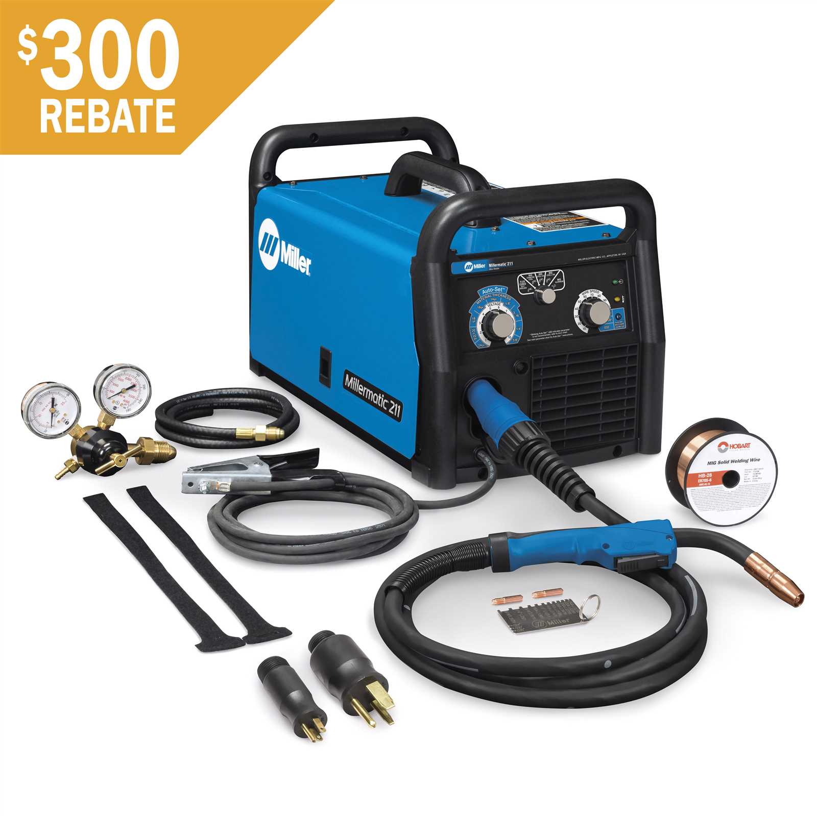
The internal mechanisms are engineered to enhance the welding process, allowing for adjustments in speed, pressure, and output. This includes a wire feed system, a regulator, and other critical parts that ensure stability during operation. Proper care of these systems ensures long-lasting use and consistent results.
Understanding the Function of Key Parts
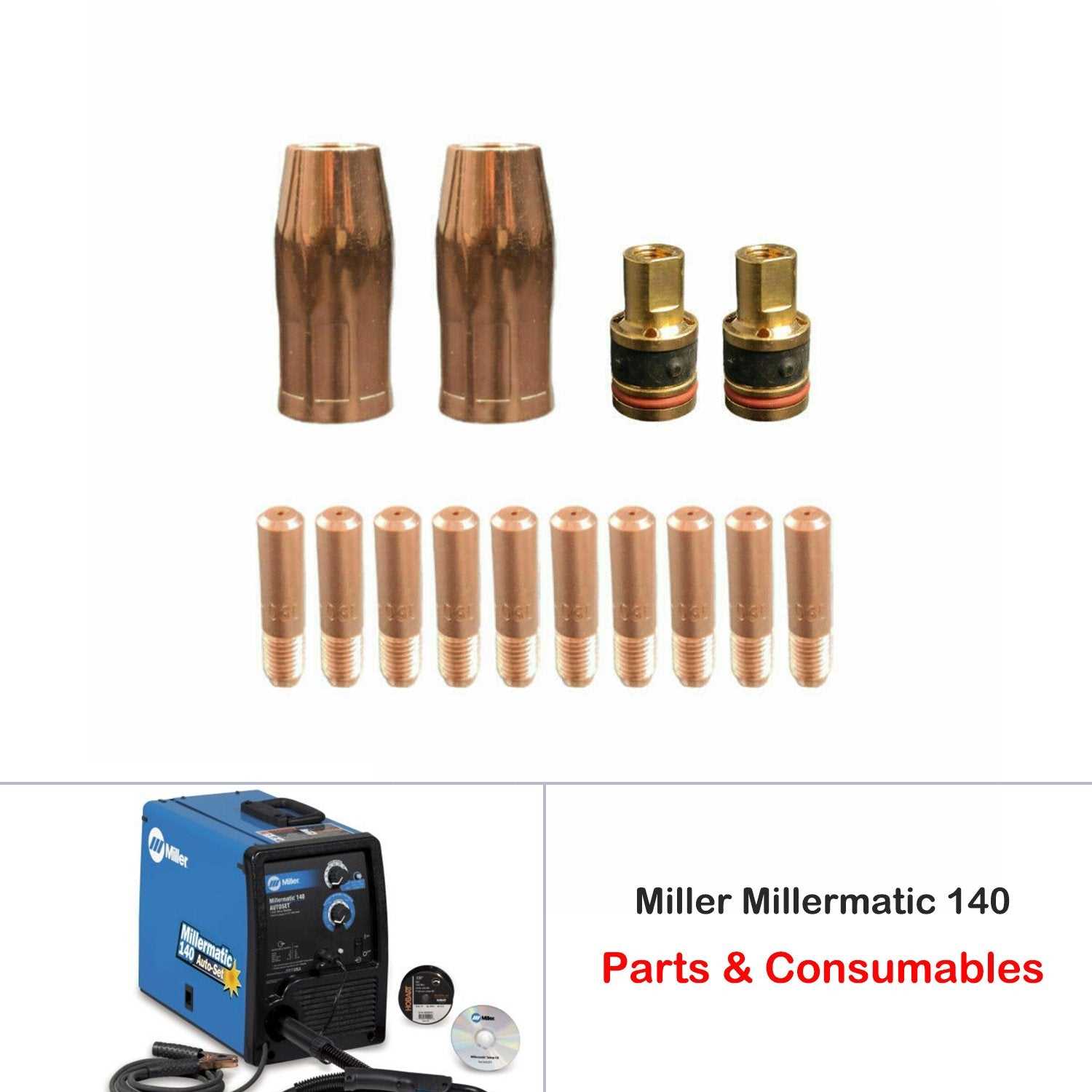
In this section, we will explore the essential components and their roles in ensuring smooth operation of the machine. Each element plays a critical role in maintaining efficiency and durability, contributing to the overall performance of the system.
- Control Panel: This is the central interface that allows users to adjust settings and monitor performance during operation.
- Power Source: Responsible for providing the necessary energy to run the equipment, ensuring consistent functionality.
- Wire Feeder: This mechanism delivers the material needed for continuous operation, maintaining steady output.
- Nozzle: Positioned to direct the flow accurately, enhancing precision and reducing waste.
- Cooling System: Designed to prevent overheating, it extends the lifespan of the machine by maintaining optimal temperature.
Identifying Common Replacement Components
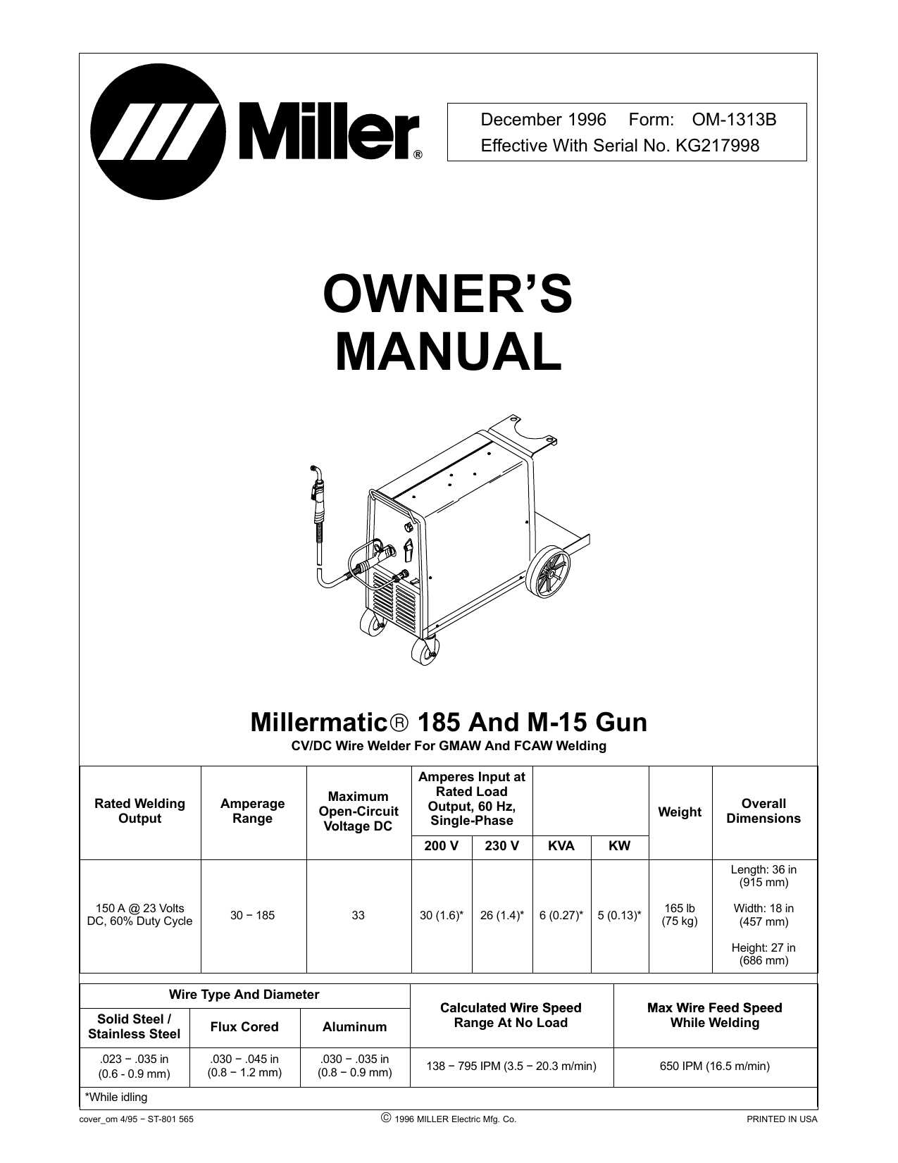
Understanding the key components that require frequent replacement is crucial for ensuring the longevity and proper function of your equipment. Regular maintenance often reveals wear and tear on specific elements, which can be addressed to avoid larger issues.
| Component | Description | Signs of Wear |
|---|---|---|
| Control Panel Knob | The knob allows users to adjust settings and fine-tune performance. | Looseness or difficulty in turning. |
| Wire Feeder Mechanism | Responsible for guiding the wire smoothly during operation. | Inconsistent feed rate or jamming. |
| Gun Trigger | The trigger activates the main operation, controlling the flow of wire and gas. | Delayed response or unresponsive activation. |
| Contact Tip | Ensures consistent contact between the wire and the workpiece. | Burning or erosion at the tip. |
How to Locate Parts on the Diagram
Understanding how to identify components in a visual layout is essential for efficient maintenance and repairs. By carefully examining the layout and following a systematic approach, you can easily pinpoint the specific item you’re searching for.
Step-by-Step Navigation
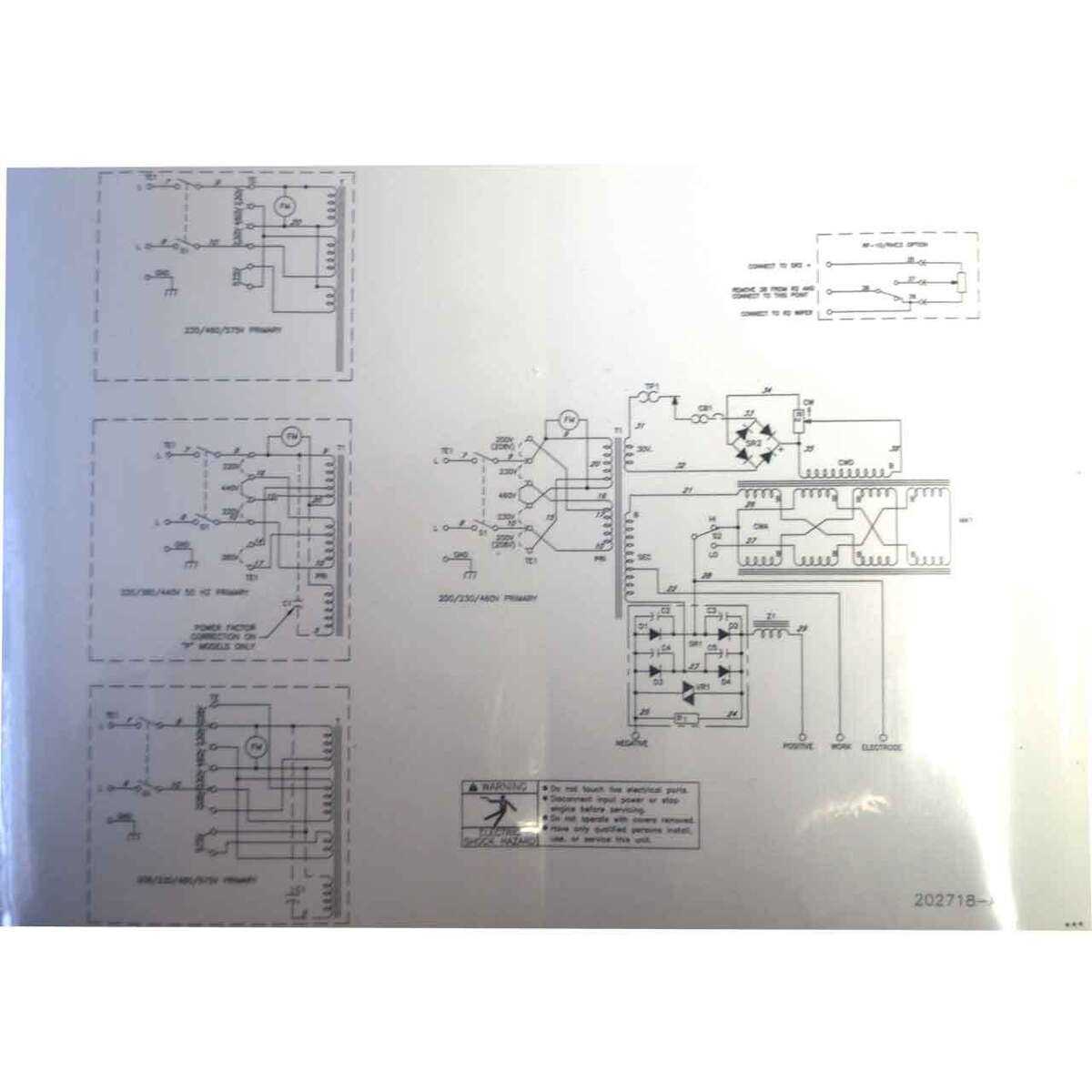
- Start by familiarizing yourself with the different sections of the layout, often grouped by functionality or placement.
- Use any provided labels or numbering systems to help guide you through the layout.
- Look for reference points such as larger, easily recognizable items that can help you orient yourself within the layout.
Using Visual Cues
- Pay attention to size and shape, as these often indicate the type of item.
- Groupings of similar items can give clues about the area you are searching in.
- Symbols or icons might highlight important details or functions that help distinguish different sections.
Troubleshooting Issues with Internal Parts
Identifying and resolving malfunctions within key internal components can significantly improve the overall performance of a machine. Common issues may arise due to wear and tear, incorrect assembly, or faulty connections. Addressing these challenges requires a systematic approach, focusing on examining each internal element for signs of damage or improper function.
| Problem | Possible Cause | Solution |
|---|---|---|
| Overheating | Blocked airflow or faulty cooling system | Clean vents, inspect cooling system for issues |
| Intermittent performance | Loose or corroded connections | Tighten or replace faulty connections |
| No response from the system | Power supply issue or damaged component | Check power connections and replace damaged parts |
| Unusual noises | Worn-out internal components | Inspect and replace damaged parts |
Maintenance Tips for Long-Lasting Components
Ensuring the longevity of mechanical elements is essential for optimal performance and efficiency. Regular upkeep not only enhances functionality but also prevents unexpected failures that can lead to costly repairs. Implementing simple maintenance routines can significantly extend the lifespan of these vital components.
1. Regular Cleaning: Accumulated dust and debris can impede operation and cause wear. Routinely clean surfaces and mechanisms to maintain smooth functionality.
2. Lubrication: Applying the right lubricant reduces friction and prevents corrosion. Be sure to use appropriate products and follow manufacturer recommendations.
3. Inspection: Conduct periodic checks for signs of wear or damage. Identifying issues early can prevent more serious problems from developing.
4. Proper Storage: When not in use, store equipment in a dry, clean environment. Protecting components from moisture and contaminants helps maintain their integrity.
5. Follow Guidelines: Adhere to operational guidelines provided by the manufacturer. Understanding specific requirements ensures components function optimally and reduces the risk of premature failure.
Signs Your Millermatic Needs New Parts
Over time, every equipment can exhibit signs of wear and tear, indicating that certain components may require replacement. Recognizing these signals early can help maintain performance and prolong the lifespan of your machine.
One of the first indications that something might be amiss is inconsistent output. If you notice fluctuations in quality or power while operating, it could suggest that critical components are beginning to fail. Additionally, if the equipment produces unusual noises or vibrations during use, this may signal underlying issues that need immediate attention.
Another important factor to consider is the presence of excessive smoke or a burning smell. These symptoms often point to overheating or electrical malfunctions, which can lead to more severe damage if not addressed promptly. Lastly, frequent tripping of circuit breakers can indicate that your device is drawing too much power, suggesting the need for inspection and potential replacement of worn-out elements.
Best Practices for Assembling the Machine
Proper assembly of any complex apparatus is crucial for its efficient operation and longevity. Following a systematic approach can significantly reduce errors and enhance the performance of the device. This section outlines essential practices that ensure a smooth assembly process, resulting in a well-functioning unit.
Begin by organizing all components in a designated workspace, ensuring everything is accessible. Review the assembly instructions thoroughly before starting. Familiarize yourself with each element and its role within the overall structure. This preparation will save time and prevent frustration during the assembly process.
Utilize appropriate tools and equipment for each task, as using the wrong tools can lead to damage or improper assembly. Take your time to align parts accurately and avoid forcing components together, as this can cause misalignment or breakage. Always check for proper fit before securing pieces in place.
As you assemble the unit, periodically review your progress against the instructions to ensure all steps are completed correctly. Once the assembly is finished, conduct a comprehensive inspection to confirm that everything is securely attached and functioning as intended. By adhering to these best practices, you can achieve a reliable and effective machine that meets your operational needs.
Exploring the Wiring Connections in the Diagram
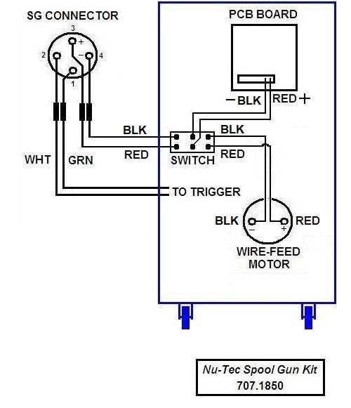
Understanding the electrical connections is crucial for anyone looking to work with welding equipment. This section delves into the intricate network of wiring illustrated in the schematic. By examining these connections, users can gain insights into the functionality and operation of the device.
Each wire and terminal plays a vital role in ensuring proper functionality, facilitating communication between various components. Identifying these connections can aid in troubleshooting and maintaining optimal performance. The schematic serves as a valuable reference, highlighting the pathways through which electrical signals flow, allowing for efficient operation of the equipment.
Through careful analysis, one can pinpoint potential issues and understand how each component interacts within the system. This knowledge not only enhances repair skills but also empowers users to make informed decisions regarding upgrades and modifications. Exploring these connections opens the door to a deeper understanding of the machinery and its capabilities.
Where to Find Genuine Millermatic Parts
Locating authentic components for your welding equipment is essential to ensure optimal performance and longevity. Quality replacements not only enhance functionality but also guarantee safety during operations. Here are some reliable sources for obtaining genuine replacements.
Authorized Dealers
One of the best ways to ensure you’re getting authentic components is to purchase from authorized dealers. They offer:
- Verified products directly from the manufacturer.
- Expert guidance and support for selecting the right components.
- Warranty options for peace of mind.
Online Retailers
Many online platforms specialize in welding equipment and supplies. When searching online, consider the following:
- Check customer reviews and ratings to assess credibility.
- Ensure the website has secure payment options.
- Look for clear return policies in case of discrepancies.
Utilizing these avenues will help you find reliable components for your welding setup, enhancing your overall experience.
Upgrading Your Millermatic 185 for Better Performance
Enhancing your welding machine can significantly improve its efficiency and output quality. By focusing on specific components and implementing upgrades, you can ensure your equipment operates at peak performance. This guide will explore various modifications that can elevate your machine’s capabilities, providing you with a competitive edge in your projects.
Assessing Your Current Setup
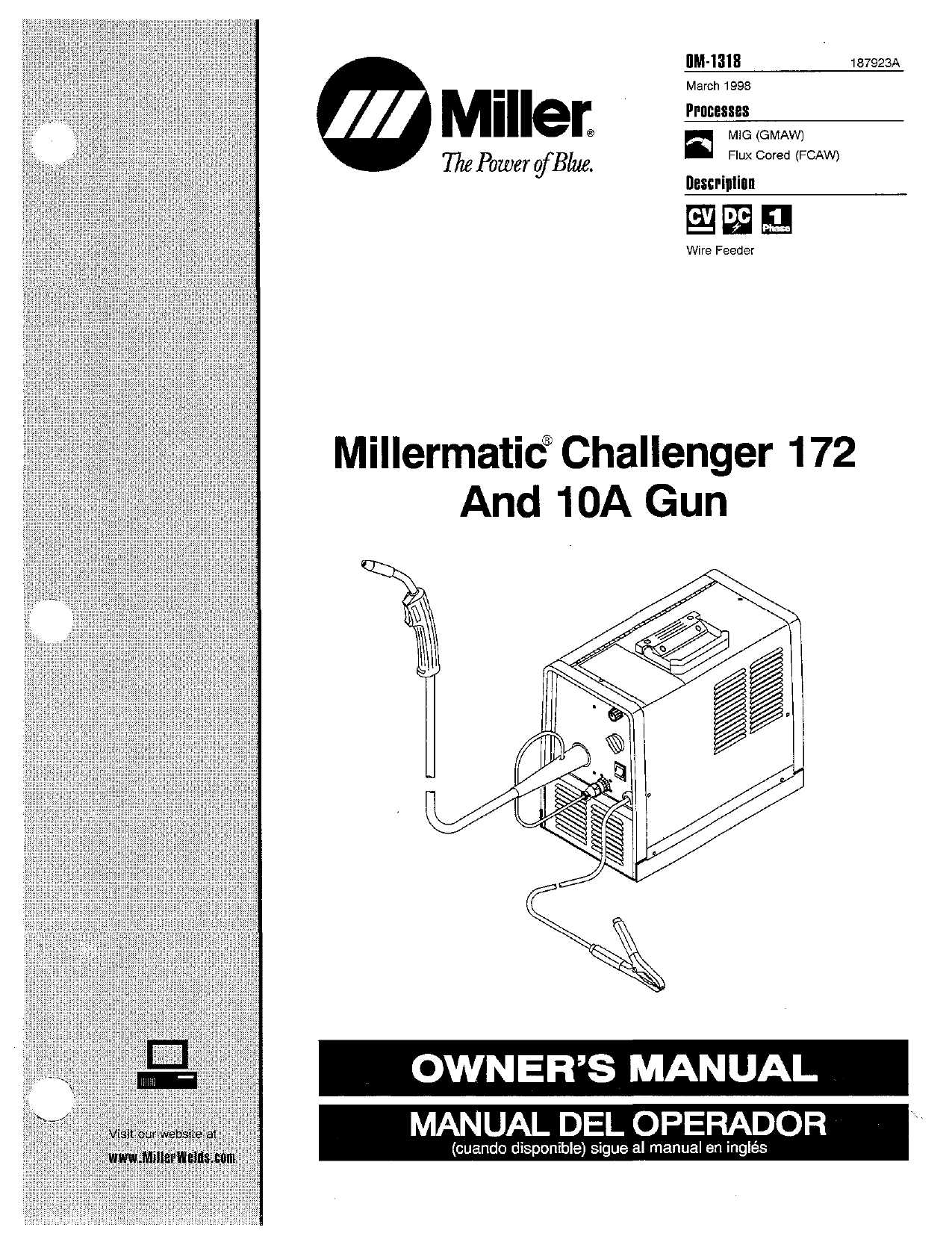
Before initiating any upgrades, it is crucial to evaluate your existing configuration. Identify areas that require improvement, such as voltage settings, feed speed, and welding technique. This assessment will guide you in selecting the most effective enhancements, ensuring you address any limitations of your current setup.
Essential Upgrades to Consider
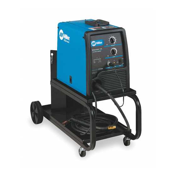
Improving the wire feed mechanism can lead to more consistent arc stability and better penetration. Consider replacing the feeder roller with a higher-quality version for improved durability. Additionally, upgrading to a digital display for voltage and amperage settings allows for greater precision in adjustments. Investing in advanced contact tips can also enhance your welding experience, as they are designed to reduce spatter and improve overall weld quality.