Understanding Goulds Jet Pump Parts Diagram for Optimal Performance
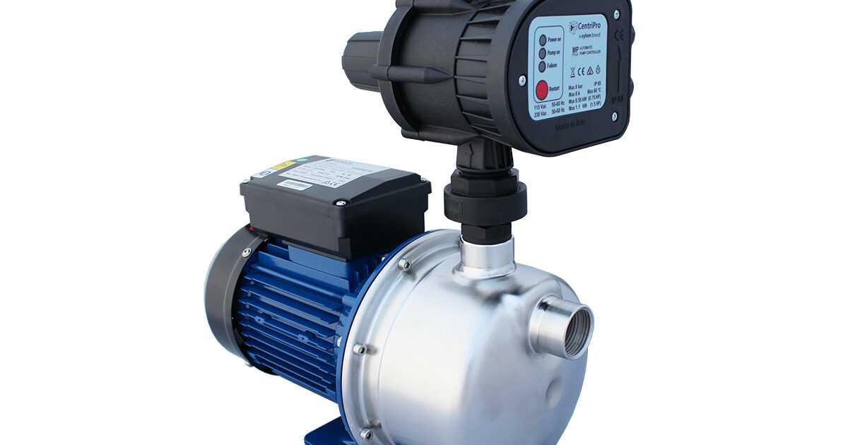
In the realm of fluid dynamics, the efficiency and reliability of water conveyance systems are paramount. A thorough understanding of the essential elements that comprise these systems is crucial for both maintenance and troubleshooting. By dissecting these components, users can ensure optimal performance and longevity of their equipment.
Detailed schematics serve as valuable tools, offering visual representations of how each component interacts within the overall assembly. This knowledge not only aids in identifying individual elements but also enhances the ability to address issues as they arise. Such diagrams facilitate a clearer grasp of the operational principles at play, leading to more effective solutions.
Additionally, being familiar with the intricacies of these systems empowers individuals to make informed decisions regarding upgrades or replacements. As technology advances, understanding the evolution of these components becomes essential for maximizing efficiency and adapting to new challenges. Ultimately, a comprehensive grasp of the elements involved will contribute significantly to the successful operation of any water transport system.
Understanding Goulds Jet Pump Mechanism
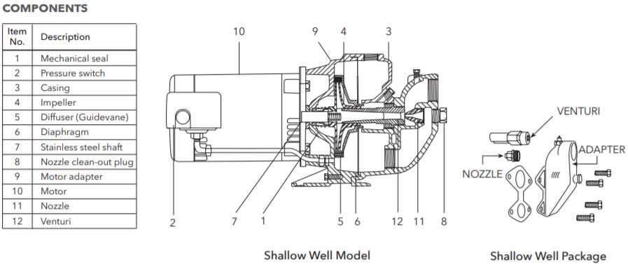
The mechanism in question operates through a fascinating interplay of components designed to elevate fluids efficiently from a source to a desired destination. This system harnesses the principles of fluid dynamics, relying on both suction and pressure to function optimally.
At the core of this assembly lies the essential element responsible for creating a vacuum effect, which draws liquid into the system. Complementary to this are various elements that enhance performance, ensuring a steady flow while minimizing turbulence. Each component plays a crucial role, from the initial intake to the final discharge, allowing for effective transportation of fluids across different terrains.
Understanding the interaction between these various parts reveals the intricacies of this engineering marvel. From the housing that encases the mechanism to the conduits that guide the flow, each section must be meticulously designed to maximize efficiency and durability. Knowledge of these dynamics not only aids in maintenance but also in optimizing the overall functionality of the system.
Components of Goulds Jet Pump
This section focuses on the essential elements that contribute to the efficient functioning of a specific type of fluid transportation device. Understanding these components is crucial for optimal operation and maintenance.
| Component | Description |
|---|---|
| Motor | Drives the mechanism, providing necessary power for operation. |
| Impeller | Transforms mechanical energy into kinetic energy, aiding in fluid movement. |
| Venturi | Creates a pressure differential that enhances fluid flow. |
| Diffuser | Converts kinetic energy back to pressure energy for efficient fluid delivery. |
| Discharge Outlet | Directs the flow of the fluid to the desired location. |
Importance of Pump Maintenance
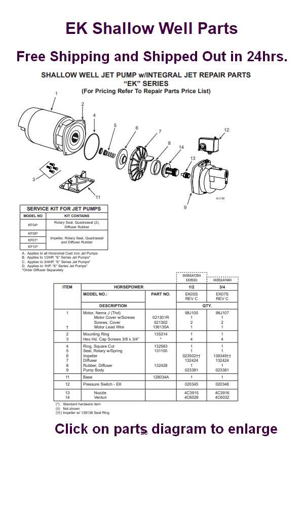
Regular upkeep of fluid transport systems is essential for ensuring optimal performance and longevity. Neglecting this critical aspect can lead to a myriad of issues, ranging from inefficiency to complete operational failure. Proactive care not only saves costs in the long run but also enhances overall system reliability.
Benefits of Regular Maintenance
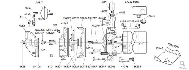
- Increased Efficiency: Well-maintained equipment operates more smoothly, reducing energy consumption and improving output.
- Extended Lifespan: Regular checks and timely repairs can significantly prolong the lifespan of the system.
- Reduced Downtime: Preventive measures help avoid unexpected breakdowns, ensuring continuous operation.
- Improved Safety: Keeping machinery in top condition minimizes the risk of accidents and hazardous situations.
Key Maintenance Practices
- Conduct routine inspections to identify wear and tear.
- Replace worn components as needed to prevent larger issues.
- Ensure proper lubrication of moving parts to reduce friction.
- Monitor system performance metrics regularly for early detection of anomalies.
Common Issues with Jet Pumps
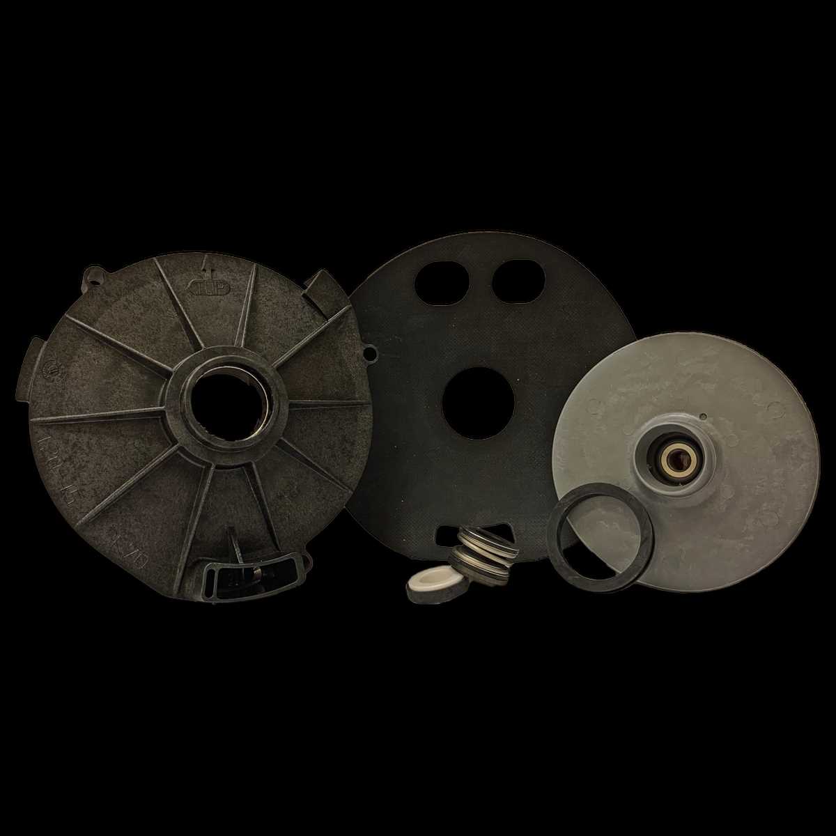
When it comes to water delivery systems, several challenges can arise that affect their efficiency and performance. Understanding these common problems is crucial for ensuring proper maintenance and timely interventions.
Low Water Flow
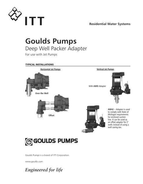
A frequent concern is inadequate water flow, which can stem from various sources. Blocked intake screens or damaged components may restrict the water supply. Regular inspection and cleaning can help prevent these issues from escalating.
Noise and Vibration
Excessive noise or vibrations during operation often indicate underlying mechanical problems. Loose fittings or misaligned parts may be the culprits. It is essential to check for these conditions periodically and tighten any loose connections to maintain optimal functionality.
Preventative measures, such as routine maintenance and timely repairs, can significantly extend the lifespan of your water delivery system. Addressing these common issues proactively ensures reliable performance and efficient operation.
Visual Guide to Pump Parts
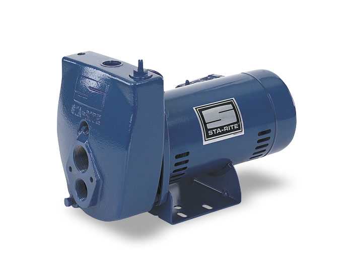
This section aims to provide a comprehensive overview of the various components that play crucial roles in the operation of fluid transfer systems. Understanding these elements is essential for efficient maintenance and troubleshooting.
Each component serves a specific function, from the inlet that draws in the liquid to the outlet that delivers it to its destination. Familiarity with these elements enhances the ability to identify issues and streamline repairs.
In addition, recognizing the interconnections between these components can help in visualizing the overall system performance. This guide will serve as a valuable resource for anyone looking to deepen their knowledge of fluid mechanics.
How to Identify Wear and Tear
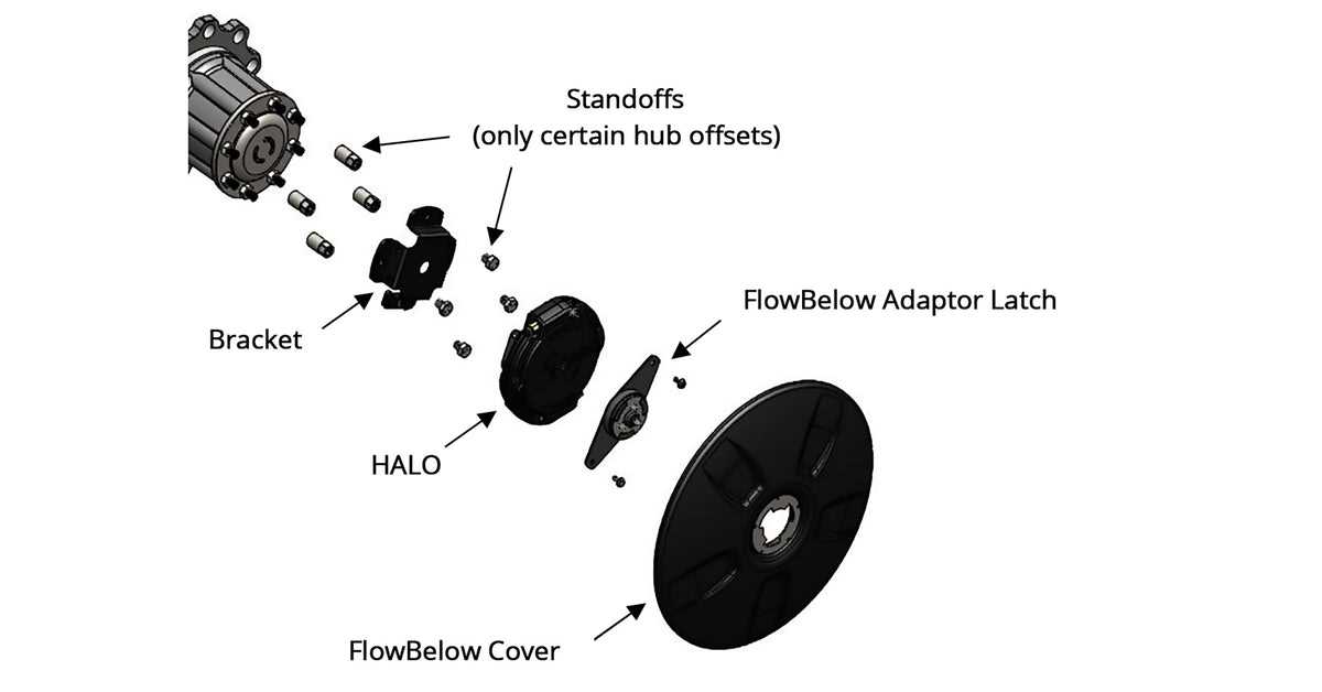
Recognizing signs of deterioration is essential for maintaining the efficiency of machinery. Various components can exhibit specific indicators that signal they may need attention. Understanding these signs can prevent larger issues and prolong the lifespan of the equipment.
Common Signs of Deterioration
Look for the following symptoms when inspecting your machinery:
| Indicator | Description |
|---|---|
| Noise | Unusual sounds during operation may indicate wear. |
| Vibration | Excessive movement can suggest imbalance or wear. |
| Leakage | Fluid leaks often point to seal deterioration. |
| Surface Damage | Cracks or corrosion on surfaces can reveal wear. |
Routine Inspection Tips
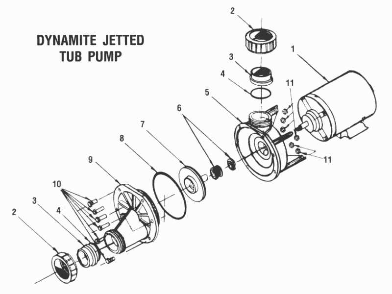
Regular examinations of the equipment, focusing on critical components, will help identify these issues early. Keeping a log of observations can aid in tracking changes over time.
Replacement Parts Overview
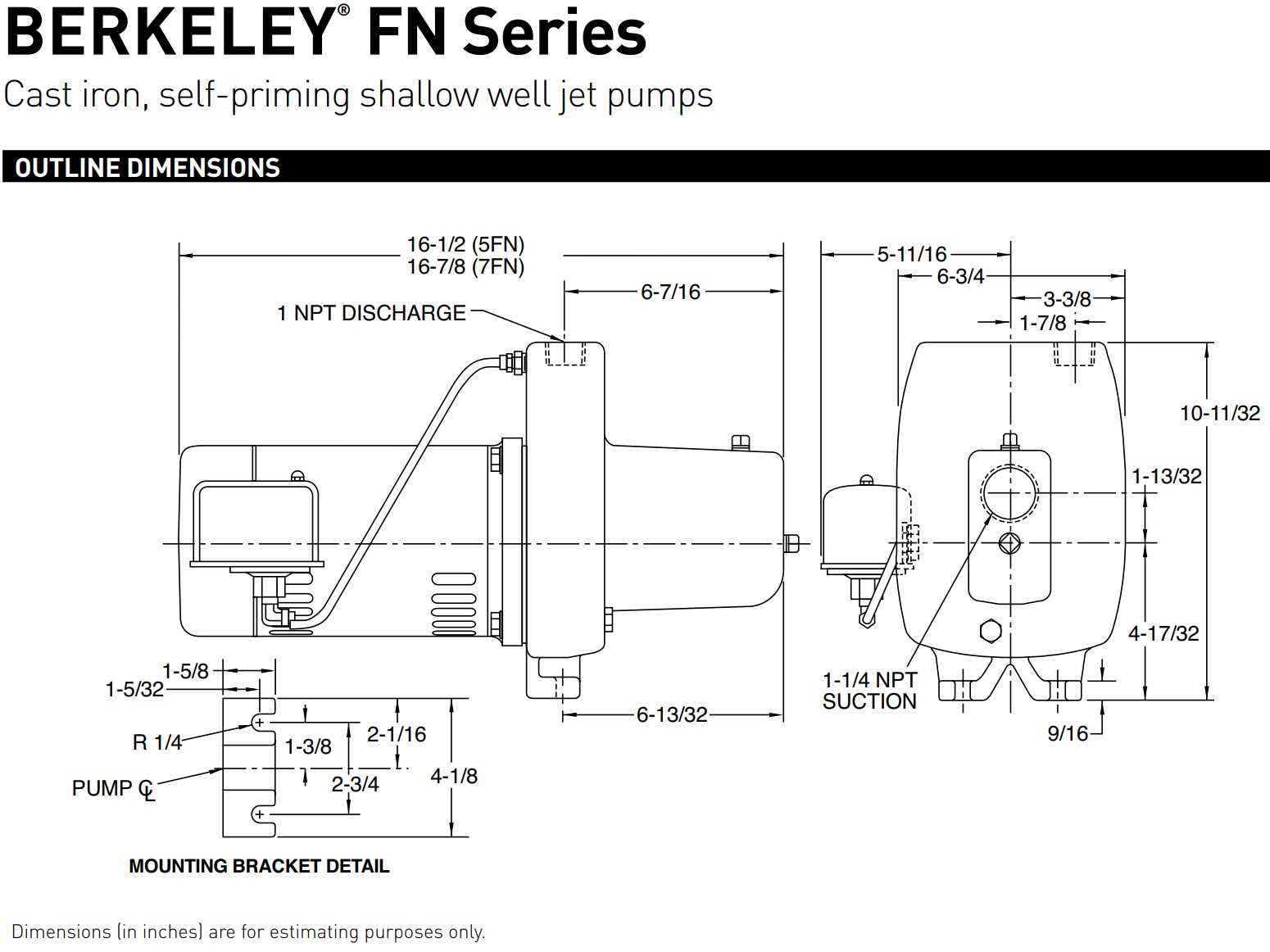
This section provides a comprehensive look at the essential components needed for maintenance and repair of water transfer systems. Understanding the significance of each element can ensure optimal functionality and longevity.
Key Components
- Seals: Crucial for preventing leaks and maintaining pressure.
- Impellers: Vital for generating the necessary flow rate.
- Casings: Provide structural integrity and house the inner workings.
- Filters: Essential for keeping debris out and ensuring clean operation.
Replacement Considerations
- Quality: Opt for high-grade materials to enhance durability.
- Compatibility: Ensure new components match the specifications of the system.
- Installation: Proper fitting is crucial for efficient performance.
Steps for Proper Installation
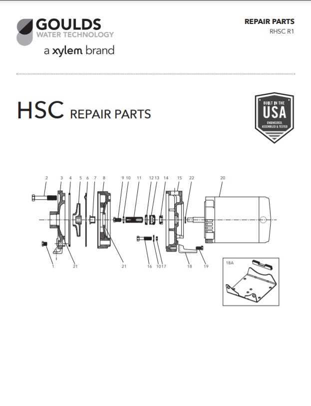
Ensuring the correct setup of your equipment is crucial for optimal performance and longevity. Following a systematic approach can prevent common issues and enhance efficiency. Below are essential steps to guide you through the installation process.
Preparation
- Gather all necessary tools and components.
- Read the manufacturer’s guidelines thoroughly.
- Choose a clean, dry workspace to avoid contamination.
Installation Process
- Begin by positioning the unit in its designated location.
- Secure all connections, ensuring they are tight and leak-proof.
- Check for any obstructions that could impede function.
- Test the system for leaks or irregularities before finalizing.
- Calibrate the settings according to the operational requirements.
Following these steps meticulously will contribute to the ultimate effectiveness of your installation.
Troubleshooting Common Pump Problems

Understanding the common issues that arise in fluid moving systems is essential for maintaining efficiency and performance. By identifying symptoms and applying systematic approaches, operators can effectively resolve these challenges and ensure optimal functionality.
Identifying Symptoms
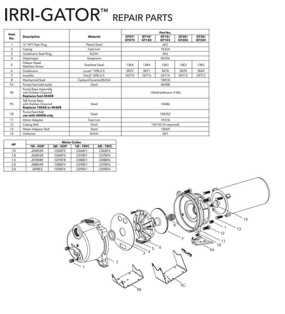
Begin by observing unusual behaviors such as irregular flow rates or unexpected noises. Vibrations or fluctuations can indicate misalignment or wear. Regular monitoring will help in pinpointing these issues before they escalate.
Common Issues and Solutions
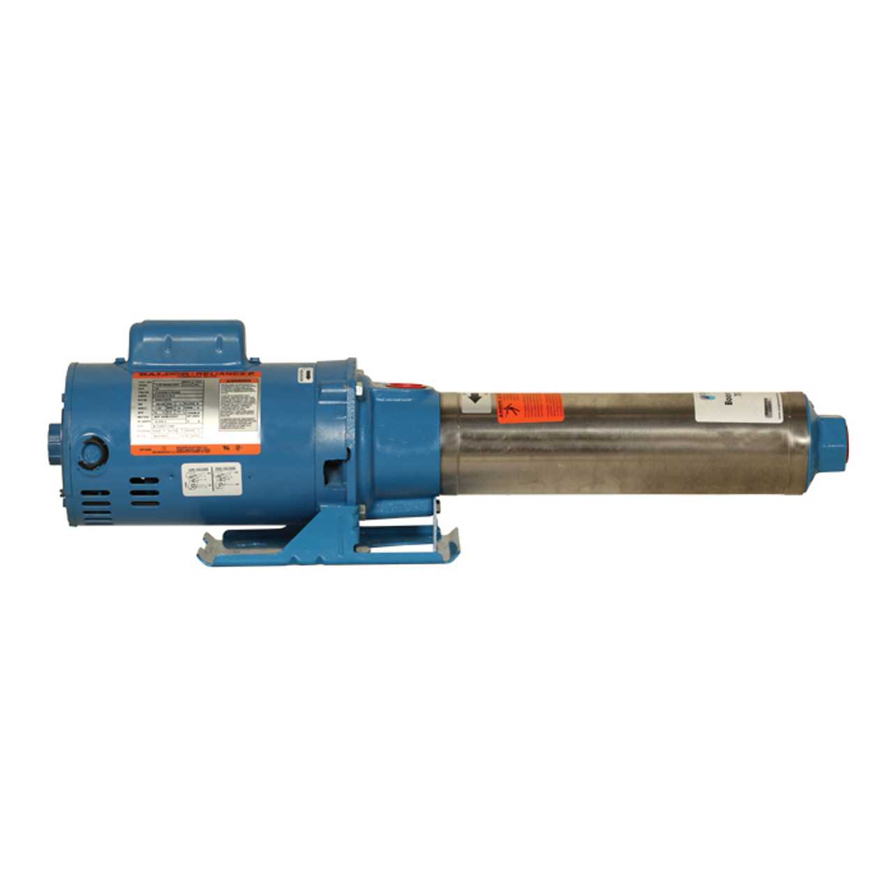
One prevalent problem is cavitation, which occurs when vapor bubbles form and collapse within the mechanism, causing damage. To address this, check the inlet pressure and ensure it meets the manufacturer’s specifications. Another frequent challenge is leakage; inspect seals and fittings to identify and replace worn components promptly.
Upgrading Your Pump System
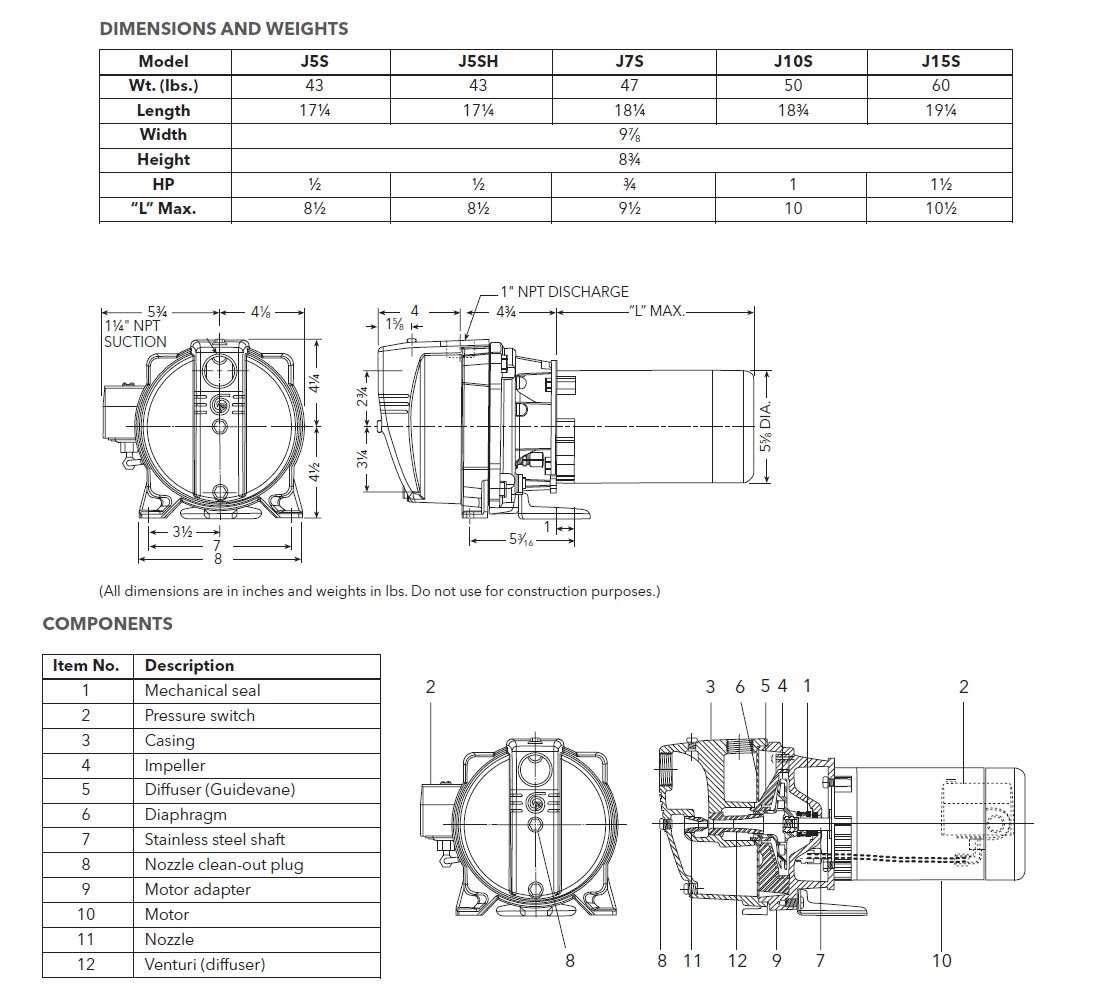
Enhancing your fluid transfer system can significantly improve efficiency, reliability, and overall performance. Whether you’re facing challenges with an outdated setup or simply seeking to optimize operations, a thoughtful upgrade can make a substantial difference.
Here are key considerations to keep in mind when planning your enhancement:
- Assess Current Performance: Evaluate the existing system’s performance metrics to identify areas for improvement.
- Set Clear Objectives: Define what you aim to achieve with the upgrade, such as increased capacity or reduced energy consumption.
- Research Modern Alternatives: Explore newer technologies that offer advanced features, such as variable speed controls and improved efficiency ratings.
When implementing changes, consider the following steps:
- Consult with Experts: Engage with professionals who can provide insights and recommendations based on your specific needs.
- Plan the Upgrade Process: Develop a timeline and strategy for installation to minimize downtime and disruptions.
- Test the New System: After installation, conduct thorough testing to ensure that the system operates as intended and meets performance goals.
By taking a strategic approach to upgrades, you can enhance your fluid management system, leading to improved efficiency and longevity.